Input tuning circuit of television tuner

Inactive Publication Date: 2011-12-01
ALPS ALPINE CO LTD
View PDF4 Cites 0 Cited by
  • Summary
  • Abstract
  • Description
  • Claims
  • Application Information

AI Technical Summary

Benefits of technology

[0006]In the related art input tuning circuits, there has been a requirement for improved interference characteristics during UHF band reception. Although the interference characteristics can be improved by adding a trap circuit to the second tuning circuit unit, which is on the UHF receiver side, adding a trap circuit may result in increases in the size and cost of the circuit.
[0007]In view of this, the present invention provides an input tuning circuit that can improve the interference characteristics during UHF band reception while suppressing an increase in cost and realizing a reduction in size.
[0009]According to this configuration, during reception in the third frequency band, the first switching device is turned on, thereby making the second tuning circuit unit be tuned to the third frequency band, and the second switching device is turned on, thereby forming a trap in a frequency range lower than the frequencies of reception signals in the third frequency band, in the first tuning circuit unit connected to the second tuning circuit unit. Hence, the Q factor of the second tuning circuit unit is improved, whereby the interference characteristics are improved. In addition, since an existing VHF tuning circuit unit is utilized as a trap circuit to form a trap during reception in the third frequency band, there is no increase in the number of components, an increase in cost can be limited to a minimum, and an increase in the size of the circuit can be prevented.
[0013]According to this configuration, it is preferable that a capacitor be connected in parallel with the variable capacitance device during reception in the first and second frequency bands, and the capacitor be disconnected during reception in the third frequency band so as to lower the capacitance. By making the capacitance of the first tuning circuit unit lower during reception in the third frequency band, the first tuning circuit unit can be made to operate as a trap circuit in a frequency range lower than the reception frequency of the third frequency band, whereby the Q factor of the second tuning circuit unit can be improved and the interference characteristics can be further improved.
[0017]According to the present invention, in a band-switching input tuning circuit, the interference characteristics can be improved during reception in the UHF band while suppressing an increase in cost and reducing the size of the circuit.

Problems solved by technology

Although the interference characteristics can be improved by adding a trap circuit to the second tuning circuit unit, which is on the UHF receiver side, adding a trap circuit may result in increases in the size and cost of the circuit.

Method used


Image

  • Input tuning circuit of television tuner
  • Input tuning circuit of television tuner
  • Input tuning circuit of television tuner

Examples


first embodiment

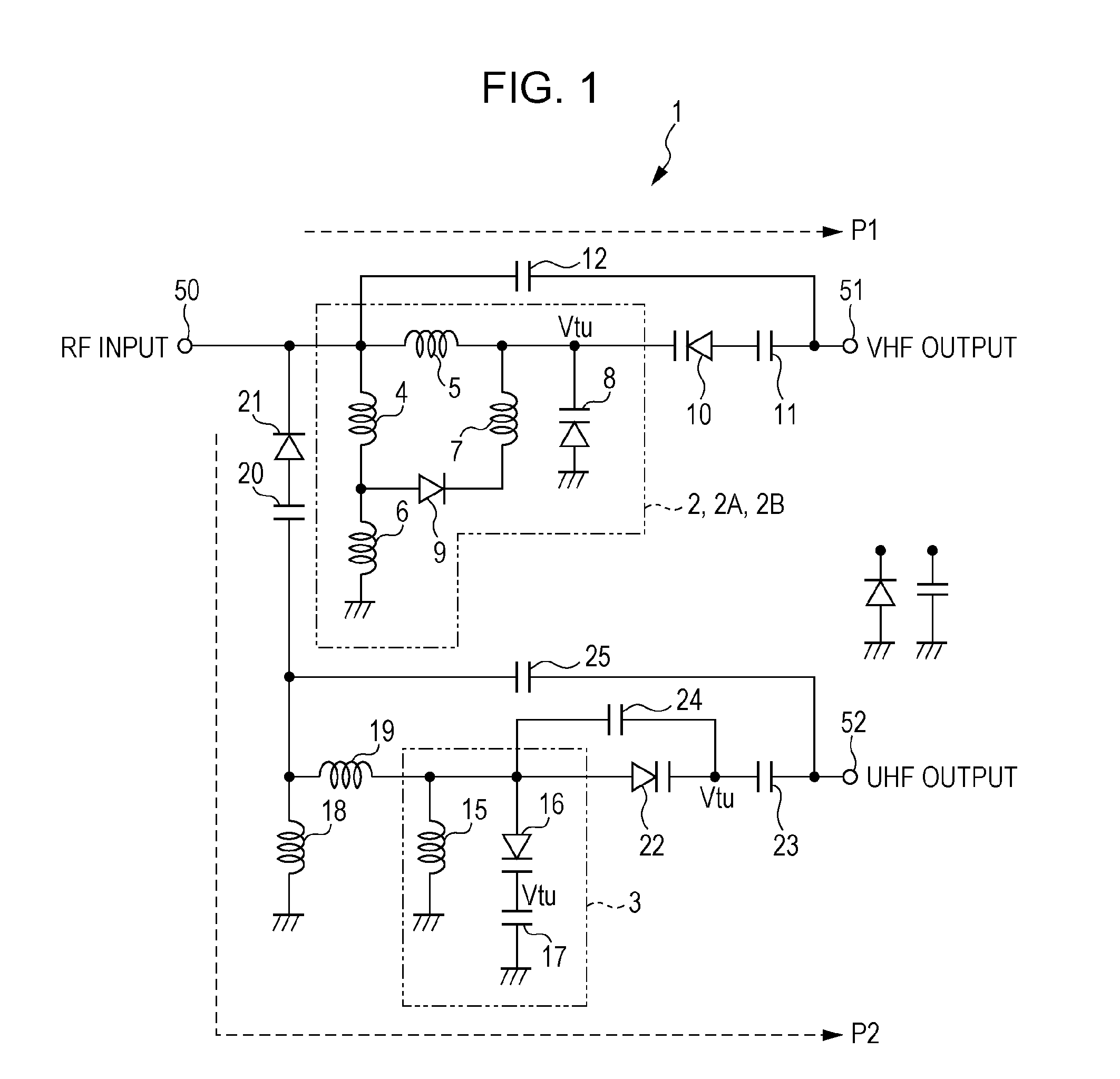
[0027]FIG. 1 illustrates a circuit configuration of an input tuning circuit according to a first embodiment of the present invention. In FIG. 1, an input tuning circuit 1 of the present embodiment is a band-switching tuning circuit which can be tuned to each of the VHF-Low band, VHF-High band, and UHF band, and includes a VHF tuning circuit unit 2 tuned to the signals in the VHF-Low / High bands and a UHF tuning circuit unit 3 tuned to signals in the UHF band.

[0028]The VHF tuning circuit unit 2 preferably includes tuning inductors 4 and 5 (first and second inductors), first ends of which are both connected to an RF input terminal 50, a tuning inductor (third inductor) 6 connected between the second end of the tuning inductor 4 and the ground, a tuning inductor (fourth inductor) 7, one end of which is connected to the second end of the tuning inductor 5, a tuning varactor diode (variable capacitance device) 8, whose cathode is connected to the second end of the tuning inductor 5 and wh...

second embodiment

[0041]FIG. 6 illustrates a circuit configuration of an input tuning circuit according to a second embodiment of the present invention. In FIG. 6, components which are common to those in FIGS. 1 and 3 are denoted by the same symbols. In the second embodiment, a VHF tuning circuit unit 2B-1 for the VHF-High band is used as a trap circuit during reception in the UHF band.

[0042]In an input tuning circuit 30 of the present embodiment, a series circuit formed of a capacitor 31 and a switching diode 32 is preferably connected in parallel with the tuning varactor diode 8 of the VHF tuning circuit unit 2 for the VHF band. The switching diode 32 is preferably turned on during reception of a television signal in the VHF-Low / High bands, thereby inserting the capacitor 31. The switching diode 32 is preferably turned off during reception in the UHF band to eliminate the influence of the capacitor.

[0043]By making the capacitance of the tuning varactor diode 8 of the VHF tuning circuit unit 2 for t...

third embodiment

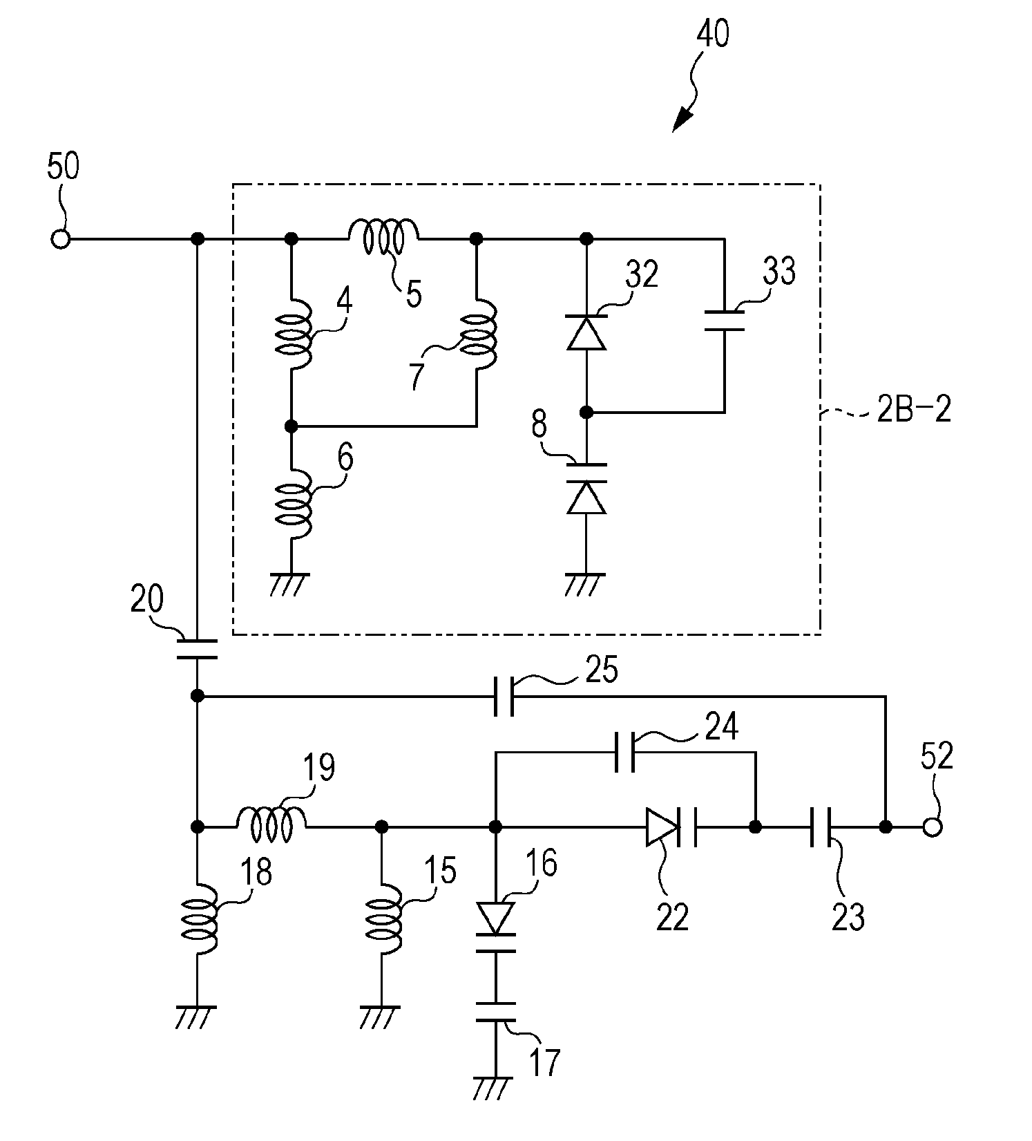
[0047]FIG. 8 illustrates a circuit configuration of an input tuning circuit according to a third embodiment of the present invention. In FIG. 8, components which are common to those illustrated in FIGS. 1, 3, and 6 are denoted by the same symbols. In the third embodiment, a VHF tuning circuit unit 2B-2 for the VHF-High band is utilized as a trap circuit during reception in the UHF band.

[0048]In an input tuning circuit 40 of the present embodiment, a parallel circuit formed of a capacitor 33 and the switching diode 32 is preferably connected in series with the tuning varactor diode 8 of the VHF tuning circuit unit 2. The switching diode 32 is preferably turned on during reception of a television signal in the VHF-Low / High bands, thereby making the capacitor 33 be in a disconnected state for high frequencies. The switching diode 32 is preferably turned off during reception in the UHF band to connect the capacitor 33. In other words, connection / disconnection of the capacitor 33 to / from...


PUM


Abstract

In an input tuning circuit, during reception of a television signal in the UHF band, a second tuning circuit unit is tuned to the UHF band by turning on a first switching diode, and a first tuning circuit unit is made to operate as a trap circuit in a frequency range lower than the UHF band by turning on a second switching diode. As a result, the transmission characteristics of the second tuning circuit unit become narrow and interference characteristics are improved. In addition, since a dedicated trap circuit need not be separately provided, an increase in cost is limited to a minimum and an increase in size is prevented.

Description

CLAIM OF PRIORITY[0001]This application claims benefit of Japanese Patent Application No. 2010-119254 filed on May 25, 2010, which is hereby incorporated by reference.BACKGROUND OF THE INVENTION[0002]1. Field of the Invention[0003]The present invention relates to input tuning circuits that can be used in input stages of television tuners.[0004]2. Description of the Related Art[0005]Existing related art input tuning circuits of television tuners include a band-switching input tuning circuit configured to be tuned to each of the VHF-Low band, VHF-High band, and UHF band (refer to Japanese Registered Utility Model No. 3101830, for example). This band-switching input tuning circuit includes a first tuning circuit unit for tuning to television signals in the VHF-Low / High bands and a second tuning circuit unit for tuning to television signals in the UHF band, and the first and second tuning circuit units are switched using switching means such as a switching diode.SUMMARY OF THE INVENTION...

Claims


Application Information

Patent Timeline
IPC IPC(8): H04N5/50
CPCH03J5/244H04N21/4263H04N5/50H04N5/455
Inventor HASHIMOTO, AKIRA
Owner ALPS ALPINE CO LTD
Why Eureka
Try Eureka