
Power terminal

a power terminal and power supply technology, applied in the field of terminals, can solve the problems of reducing electrical conductivity, reducing spring force, and copper being susceptible to relaxation

Active Publication Date: 2011-03-31
LEAR CORP
View PDF64 Cites 74 Cited by
  • Summary
  • Abstract
  • Description
  • Claims
  • Application Information

AI Technical Summary

Problems solved by technology

However, copper is susceptible to relaxation (i.e., loss of spring force) as the temperature increases.
Relaxation of the female terminals decreases the overall contact area with the male blades, resulting in reduced electrical conductivity, increased resistance, and a further increase in temperature.
Therefore, the spring force cannot be further increased by simply making the terminals thicker or wider.
When copper is used, the size limitations may make the desired spring force unattainable.
On the other hand, copper alloys typically have a lower conductivity.
In automotive applications, fuses using copper alloys are typically limited to 60 amps or less.

Method used


Image

  • Power terminal
  • Power terminal
  • Power terminal

Examples


Embodiment Construction

)

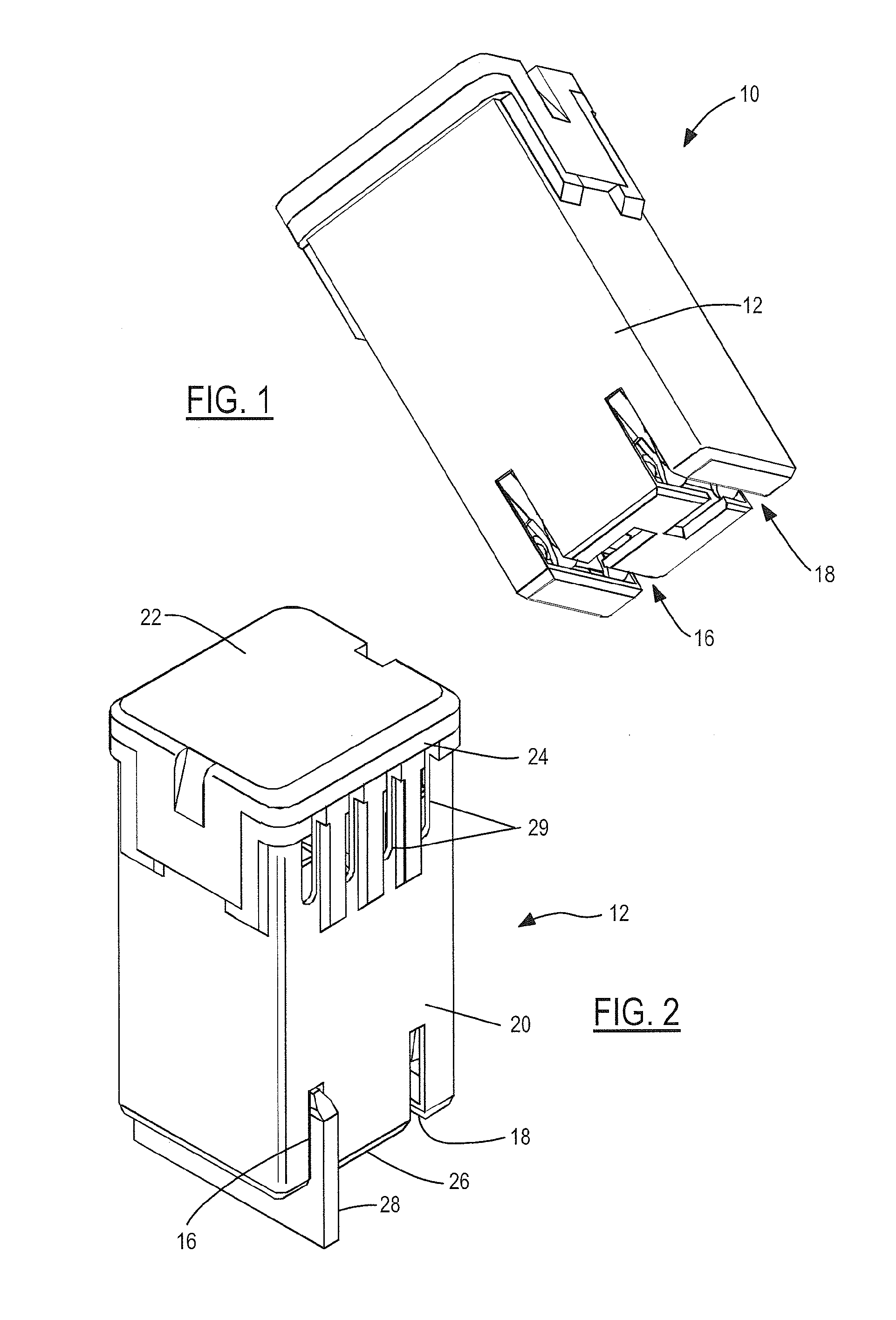
[0031]Referring now to the drawings, there is illustrated in FIG. 1 a high power fuse shown generally at 10. The high power fuse 10 includes a housing 12 and a fuse assembly 14 disposed within the housing 12. The housing 12 includes a first slot 16 for receiving a first terminal blade and a second slot 18 for receiving a second terminal blade. FIG. 2 is a perspective view of the housing 12. The housing 12 is preferably produced from two sections that include a body portion 20 and a lid portion 22. The body portion 20 is an elongated chamber that includes an open end 24 and a closed end 26. The open end 24 is of a sufficient width and length for receiving and housing the fuse assembly 14 (shown in FIG. 3) within the housing 12. The first slot 16 and the second slot 18 are formed in the closed end 26. The slots are aligned with respective receiving members for making an electrical connection with a respective terminal blade (shown generally at 28).

[0032]The lid portion 22 attaches to...


PUM

PropertyMeasurementUnit
Forceaaaaaaaaaa
Forceaaaaaaaaaa
Forceaaaaaaaaaa

Abstract

An electrical connector formed to have at least one or more pairs of opposing legs extending from a body portion where each leg extends to a contact point where an inner surface of each opposing leg contact. A spring clip can be positioned over one or more of the opposing legs to increase a compressive force. The spring clip may include an alignment feature to limit clip rotating and / or pitching.

Description

CROSS-REFERENCE TO RELATED APPLICATIONS[0001]This application is a continuation-in-part of U.S. application Ser. No. 12 / 797,735 filed Jun. 10, 2010, entitled “High Power Fuse Terminal With Scaleability”, now issued U.S. Pat. No. ______ which, in turn, claims the benefit of U.S. Provisional Application No. 61 / 187,887 filed Jun. 17, 2009, entitled “High Power Fuse Terminal With Scaleability”. This application further claims the benefit of U.S. Provisional Application 61 / 416,893 filed Nov. 24, 2010, entitled “Power Terminal”. The disclosures of which are incorporated in their entirety by reference herein.BACKGROUND OF THE INVENTION[0002]1. Field of the Invention[0003]The present invention relates to terminals, such as but not limited to power terminals operable within a vehicle to support transport of high power currents.[0004]2. Background Art[0005]Copper has good electrical conductivity properties, and has been a preferred material for the terminals. However, copper is susceptible to...

Claims


Application Information

Patent Timeline
IPC IPC(8): H01R4/48H01R43/16
CPCH01R9/245H01R13/03H01R13/112H01R13/113Y10T29/49204H01R13/187H01R13/68H01R43/16H01R13/18
Inventor GLICK, MICHAELPAVLOVIC, SLOBODANNATTER, BRANTLEYMENZIES, DAVID
Owner LEAR CORP
Features
  • Generate Ideas
  • Intellectual Property
  • Life Sciences
  • Materials
  • Tech Scout
  • Unparalleled Data Quality
  • Higher Quality Content
  • 60% Fewer Hallucinations
Learn More