Wireless power transmission/reception apparatus and method

Active Publication Date: 2011-04-07
WITS CO LTD
View PDF3 Cites 76 Cited by
  • Summary
  • Abstract
  • Description
  • Claims
  • Application Information

AI Technical Summary

Benefits of technology

[0016]The wireless power reception unit includes a second resonance antenna comprised of an inductor and a capacitor, and configured to receive the wireless power signal from the wireless power transmission unit using resonance frequency depending on the inductor and the capacitor in a magnetic resonance manner and return the remaining wireless power signal to the wireless power transmission unit; a power signal converter connected to each of a plurality of power consumption devices, configured to convert the wireless power signal received through the seco

Problems solved by technology

However, most communication information devices still depend on batteries and are supplied with power through power cords, and thus the use of communication information devices is limited.
Therefore, the environment of a wireless information network cannot be actually freed from this limitation until the problem of terminal power is solved.
However, radio reception technology has high radiation loss due to the consumption of power by the air, and thus the efficiency of power transmission is limited.
However, magnetic induction technology is disadvantageous in that the primary coil of the transmitting end and the secondary coil of the receiving end must be located adjacent to each other within a short distance of about several mm so as to transmit power, in that the efficiency of power transmission rapidly changes according to the alignment of the primary coil of the transmitting end and the secondary coil of the receiving end, and in that the amount of heat generated is large.
That is, magnetic induction technology is disadvantageous because the efficiency of power transmission rapidly changes depending on whether impedance matching has been achieved or whether the resonant frequencies of the LC circuits of the transmitting and receiving ends are identical to each other.
However, when the transceivers are installed separately, problems arise in that the cost of wireless power transmission and reception units increases and the construction of the apparatus is complicated.

Method used


Image

  • Wireless power transmission/reception apparatus and method
  • Wireless power transmission/reception apparatus and method
  • Wireless power transmission/reception apparatus and method

Examples


Embodiment Construction

[0032]Reference now should be made to the drawings, in which the same reference numerals are used throughout the different drawings to designate the same or similar components.

[0033]Preferred embodiments of the present invention will be described in detail below with reference to the accompanying drawings.

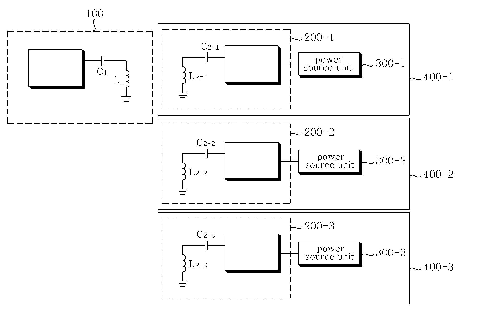
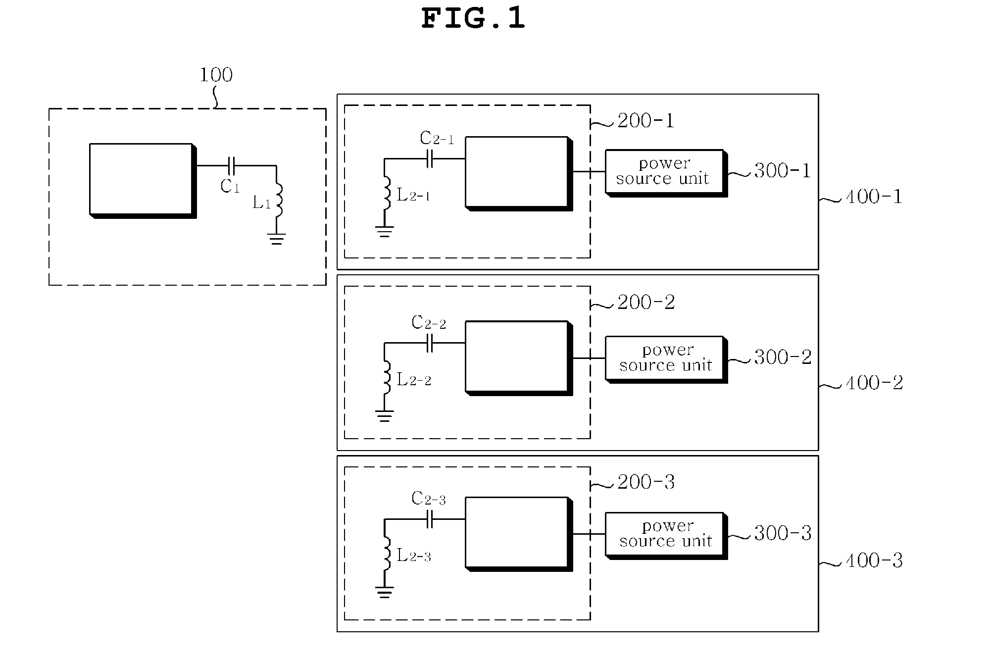
[0034]FIG. 1 is a schematic block diagram illustrating the construction of a wireless power transmission / reception apparatus according to a preferred embodiment of the present invention.

[0035]Referring to FIG. 1, the wireless power transmission / reception apparatus includes a wireless power transmission unit 100, and a plurality of wireless power reception units 200-1, 200-2 and 200-3 respectively installed in a plurality of power consumption devices 400-1, 400-2 and 400-3.

[0036]Wireless power received by the wireless power reception units 200-1, 200-2 and 200-3 installed in the power consumption devices 400-1, 400-2 and 400-3 is stored in power source units 300-1, 300-2 and 300-3.

[...


PUM


Abstract

Disclosed herein is a wireless power transmission / reception apparatus. The wireless power transmission / reception apparatus includes a wireless power transmission unit and a wireless power reception unit. The wireless power transmission unit receives power, generates a wireless power signal to be wirelessly transmitted, wirelessly transmits the generated wireless power signal in a magnetic resonance manner, receives a returned wireless power signal and detects the number of power consumption devices, and wirelessly transmits a wireless power signal using resonance frequency appropriate for the number of power consumption devices.

Description

CROSS REFERENCE TO RELATED APPLICATION[0001]This application claims the benefit of Korean Patent Application No. 10-2009-0095284, filed on Oct. 7, 2009, entitled “Wireless Power Transmission Apparatus and Method thereof,” which is hereby incorporated by reference in its entirety into this application.BACKGROUND OF THE INVENTION[0002]1. Technical Field[0003]The present invention relates generally to a wireless power transmission / reception apparatus and method, and, more particularly, to a wireless power transmission / reception apparatus and method which enable the active detection of the reception environment of the wireless power transmission / reception apparatus without using a separate wireless communication device.[0004]2. Description of the Related Art[0005]With the development of wireless communication technology, ubiquitous information environments enabling anyone to exchange desired information anytime and anywhere have been implemented. However, most communication information ...

Claims


Application Information

Patent Timeline
IPC IPC(8): H01F38/00
CPCH02J5/005H02J7/025H01F38/14H02J17/00H02J50/12H02J50/80H02J50/40H02J50/90H04B1/04H04B5/48
Inventor LEE, KWANG DUKIM, KYUNG UKKIM, JEONG HOONKIM, EUNG JU
Owner WITS CO LTD
Why Eureka
Try Eureka