Lighting fixture

a technology for lighting fixtures and fixtures, applied in the field of lighting fixtures, can solve the problems of complicated installation and non-compact appearance, and achieve the effects of compact outer appearance, reduced glare, and convenient installation

Inactive Publication Date: 2011-04-07
NOH & CHUNG
View PDF0 Cites 32 Cited by
  • Summary
  • Abstract
  • Description
  • Claims
  • Application Information

AI Technical Summary

Benefits of technology

[0010]The present invention is directed to solving the problems of the related art as described above, and an aspect of the present invention is to provide a lighting fixture that is configured not only to reduce glare and permit easy installation, but also to have a compact outer appearance.

Problems solved by technology

In such a lighting fixture, a user passing by the lighting fixture is not only directly irradiated with light from a light source, causing glare, but the light source, a mirror and a circuit unit are also separately provided to the lighting fixture, complicating installation and resulting in a non-compact appearance.

Method used


Image

  • Lighting fixture
  • Lighting fixture
  • Lighting fixture

Examples


first embodiment

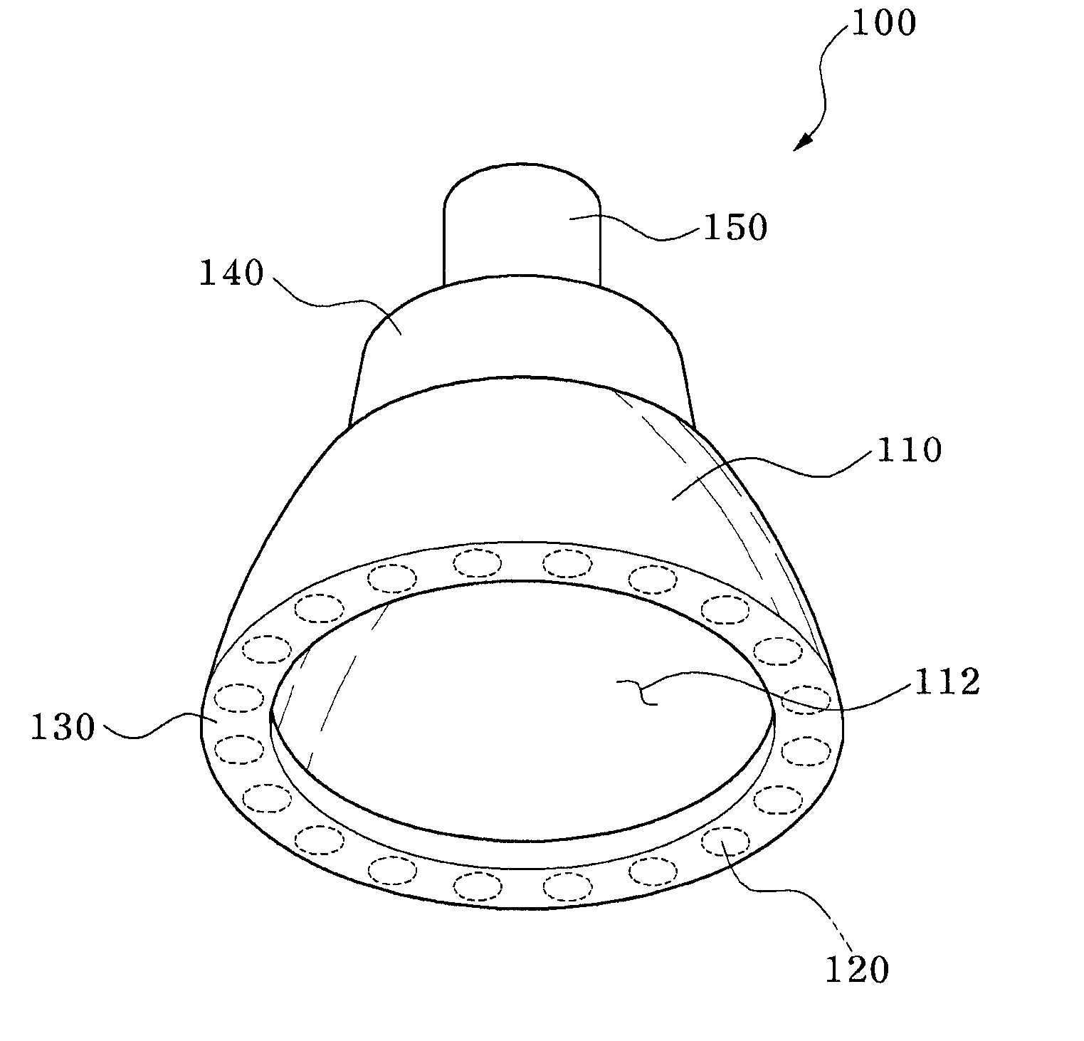
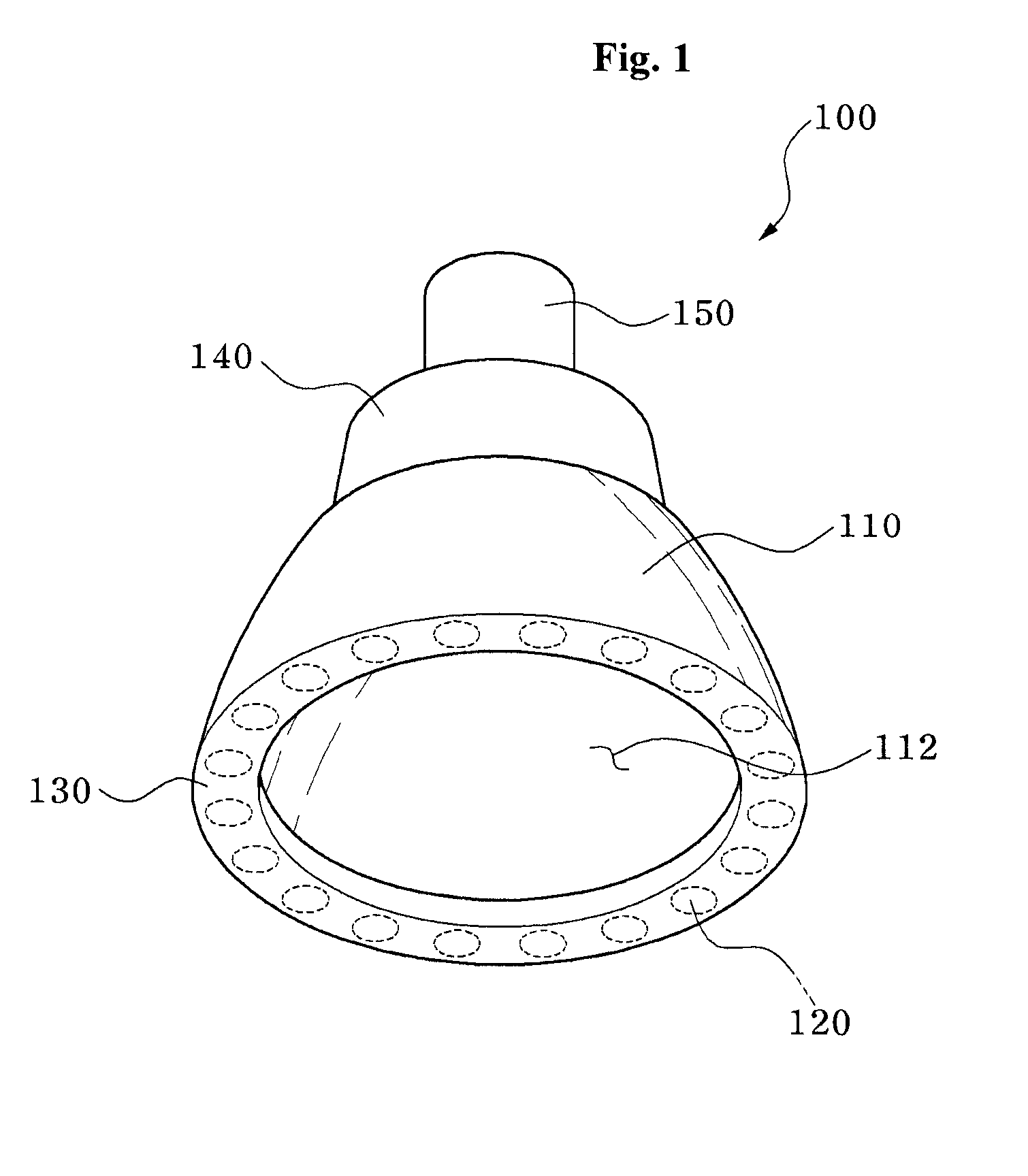
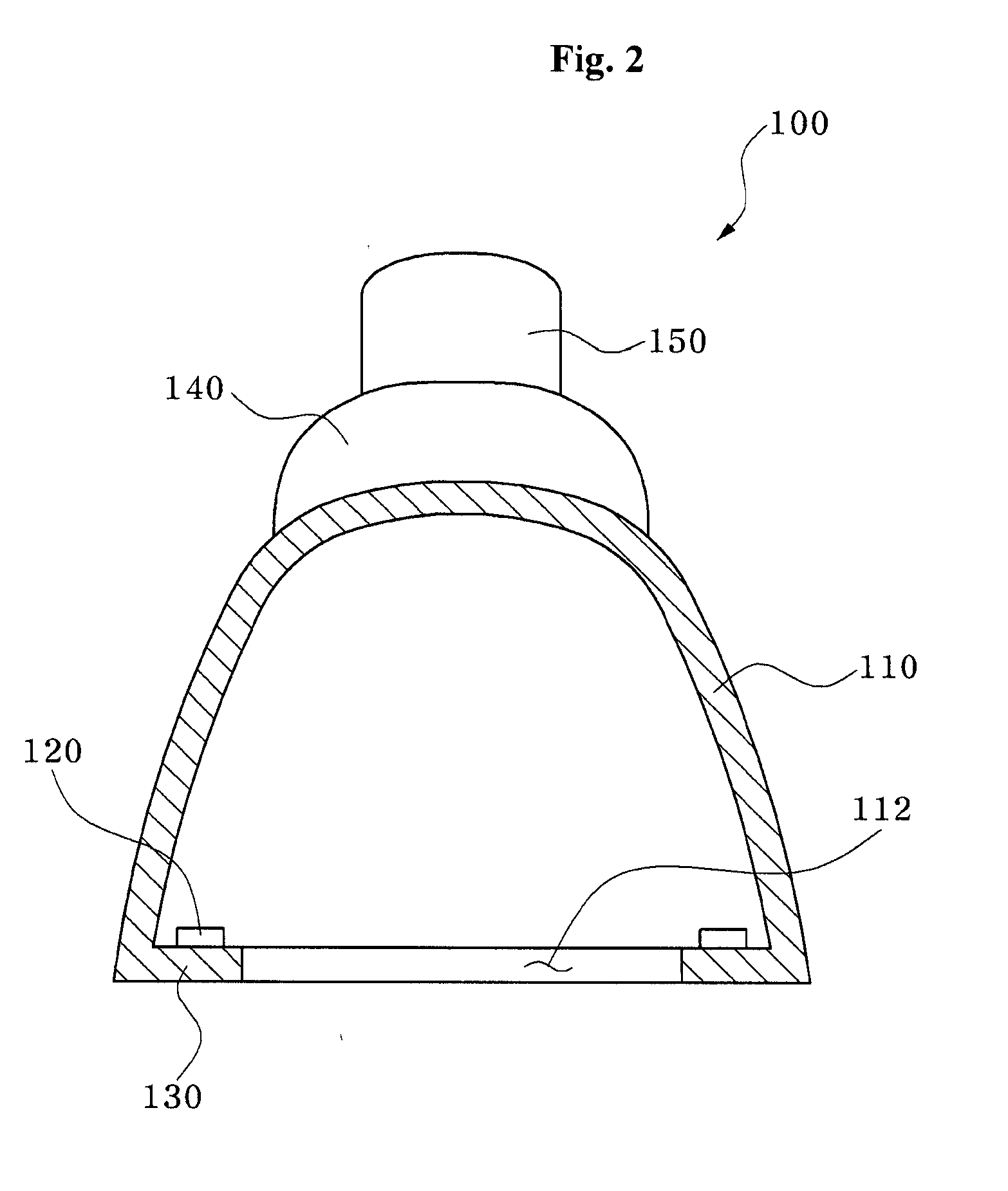
[0043]FIG. 1 is a perspective view of a lighting fixture and FIG. 2 is a sectional view of the lighting fixture of FIG. 1

[0044]Referring to FIGS. 1 and 2, the lighting fixture 100 according to the first embodiment includes a reflecting part 110, a light source 120, a mounting part 130, a circuit part 140 and a power connecting part 150.

[0045]The reflecting part 110 reflects light irradiated from the light source 120 described below. In this embodiment, the reflecting part 110 is shaped like a bell, an upper diameter of which is smaller than a lower diameter. The reflecting part 110 includes an opening 112. The opening 112 is formed to penetrate a lower side of the reflecting part 110. The reflecting part 110 may include interior reflecting plates for reflecting light or may be coated with a fluorescent material. It should be understood that the reflecting part 110 may be modified in a variety of ways.

[0046]The reflecting part 110 is made of a material capable of reflecting light ir...

second embodiment

[0057]FIGS. 3 through 6 are sectional views of a lighting fixture according to the present invention.

[0058]Referring to FIG. 3, the lighting fixture 200 according to the second embodiment includes a diffusing part 260 disposed at an opening 112. The diffusing part 260 is disposed on a lower side of a reflecting part 110 and closes the opening 112, thereby diffusing light reflected in the reflecting part 110 as the light exits the lighting fixture. In this embodiment, the diffusing part 260 may be made of a transparent or translucent material.

[0059]The diffusing part 260 may have various colors. As the diffusing part 260 has various colors, the color of the diffusing part 260 is mixed with light irradiated from a light source 120, thereby providing various colored lighting effects. The diffusing part 260 may protrude outside the reflecting part 110 and have a variable length depending upon protruded areas of the reflecting part 110 and the mounting part 130.

[0060]FIG. 4 shows another...

third embodiment

[0069]FIG. 7 is a perspective view of a lighting fixture and FIG. 8 is a sectional view of the lighting fixture of FIG. 7.

[0070]Referring to FIGS. 7 and 8, the lighting fixture 300 according to the third embodiment includes a frame unit 370. The frame unit 370 is provided to an opening 312 of a reflecting part 310 to be disposed between the reflecting part 310 and a diffusing part 260. The frame unit 270 has a ring shape corresponding to a lower side of the reflecting part 310, and partially closes the lower side of the reflecting part 310. That is, the lower side of the reflecting part 310 is closed around a lateral wall thereof by the frame unit 370, and a central portion of the lower side of the reflecting part 310 is opened.

[0071]According to this embodiment, the light source 120 is disposed on the frame unit 370 inside the reflecting part 310. Thus, the light source 120 irradiates light toward an inner surface of the reflecting part 310 and the light is reflected by the inner ...


PUM


Abstract

Disclosed is a lighting fixture. The lighting fixture includes reflecting part having an opening which penetrates the reflecting part, a light source irradiating light toward the reflecting part, a mounting part which mounts the light source thereon, a circuit part disposed at an opposite side to the opening of the reflecting part and driving the light source, and a power connecting part supplying power from outside to the circuit part. With this lighting fixture, since light irradiated from the light source is reflected by the reflecting part before exiting the lighting fixture, the light is not directly emitted towards a user, thereby reducing glare. Further, the reflecting part, the light source, the circuit part and the power connecting part are combined into an integrated module, thereby permitting easy installation while providing a compact outer appearance.

Description

BACKGROUND OF THE INVENTION[0001]1. Field of the Invention[0002]The present invention relates to lighting fixtures and, more particularly, to lighting fixtures which irradiate light.[0003]2. Description of the Related Art[0004]Lighting fixtures are used for interior decoration or to create a cozy atmosphere as well as for simple illumination. Such lighting fixtures generally include an incandescent lamp or a fluorescent lamp.[0005]Since the incandescent lamp employs simple accessories for lighting and is readily combined with other lighting devices, the incandescent lamp still occupies a significant market share despite advances in fluorescent lighting. The fluorescent lamp has merits such as higher efficiency and longer lifespan than the incandescent lamp which employs a filament, and thus, like the incandescent lamp, holds a large market share.[0006]In recent years, iodine lamps using a halogen cycle, high-efficiency halide lamps, solar-powered lamps, etc. have been developed and ...

Claims


Application Information

Patent Timeline
Patent Type & Authority Applications(United States)
IPC IPC(8): F21V29/00F21V7/00
CPCF21S8/026F21V7/0008F21V7/005F21V7/09F21V14/02F21V17/104F21V29/505F21Y2103/003F21Y2103/022F21K9/13F21K9/58F21S8/02F21Y2113/00F21Y2101/02F21K9/23F21K9/65F21Y2103/10F21Y2115/10F21Y2103/33F21Y2115/15
Inventor NOH, SI CHUNG
Owner NOH & CHUNG
Why Eureka
Try Eureka