Electro-Therapeutic Stimulator

Active Publication Date: 2011-04-07
ARP MFG
View PDF33 Cites 13 Cited by
  • Summary
  • Abstract
  • Description
  • Claims
  • Application Information

AI Technical Summary

Benefits of technology

[0005]The present invention is an electro-therapeutic stimulator and a method of using the electro-therapeutic stimulator. The electro-therapeutic stimulator provides an output signal for application with electrodes to the muscular structure of a patient. The output signal has a first controllable main pulse periodic-exponential signal such as within the range of 1 to 1000 pulses per second, and a second background pulse periodic-exponential signal at a higher frequency such as 1 to 100 kHz. In one aspect, the signal is produced using a class D amplifier an

Problems solved by technology

While the device and methods of U.S. Pat. Nos. 5,107,835 and 5,109,848 provided many beneficial results, they did not ena

Method used


Image

  • Electro-Therapeutic Stimulator
  • Electro-Therapeutic Stimulator
  • Electro-Therapeutic Stimulator

Examples


Embodiment Construction

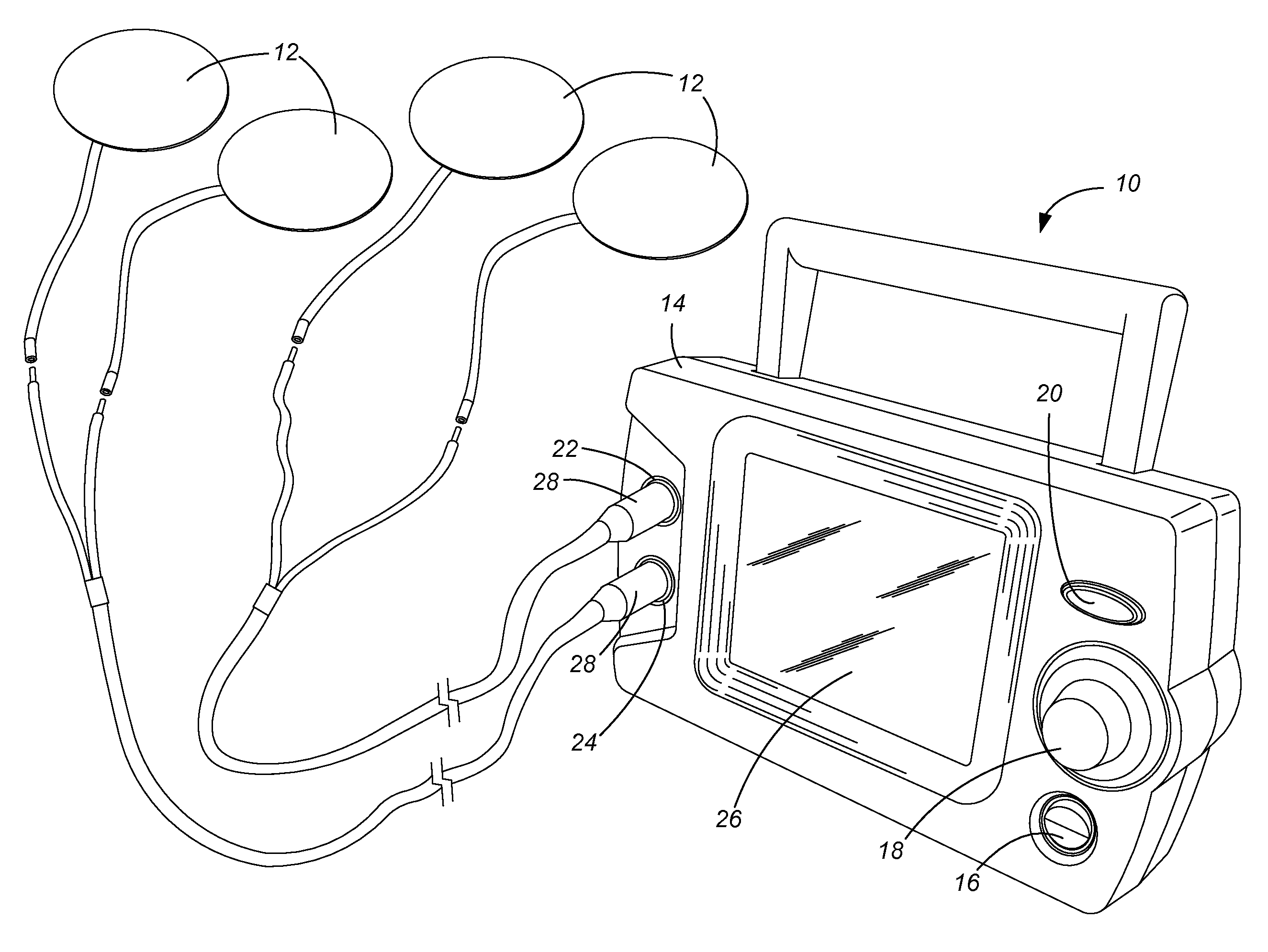
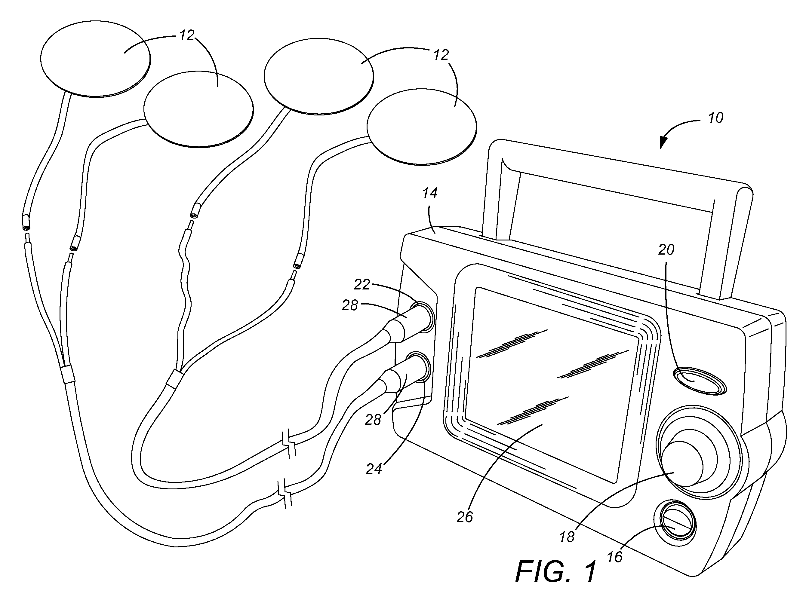
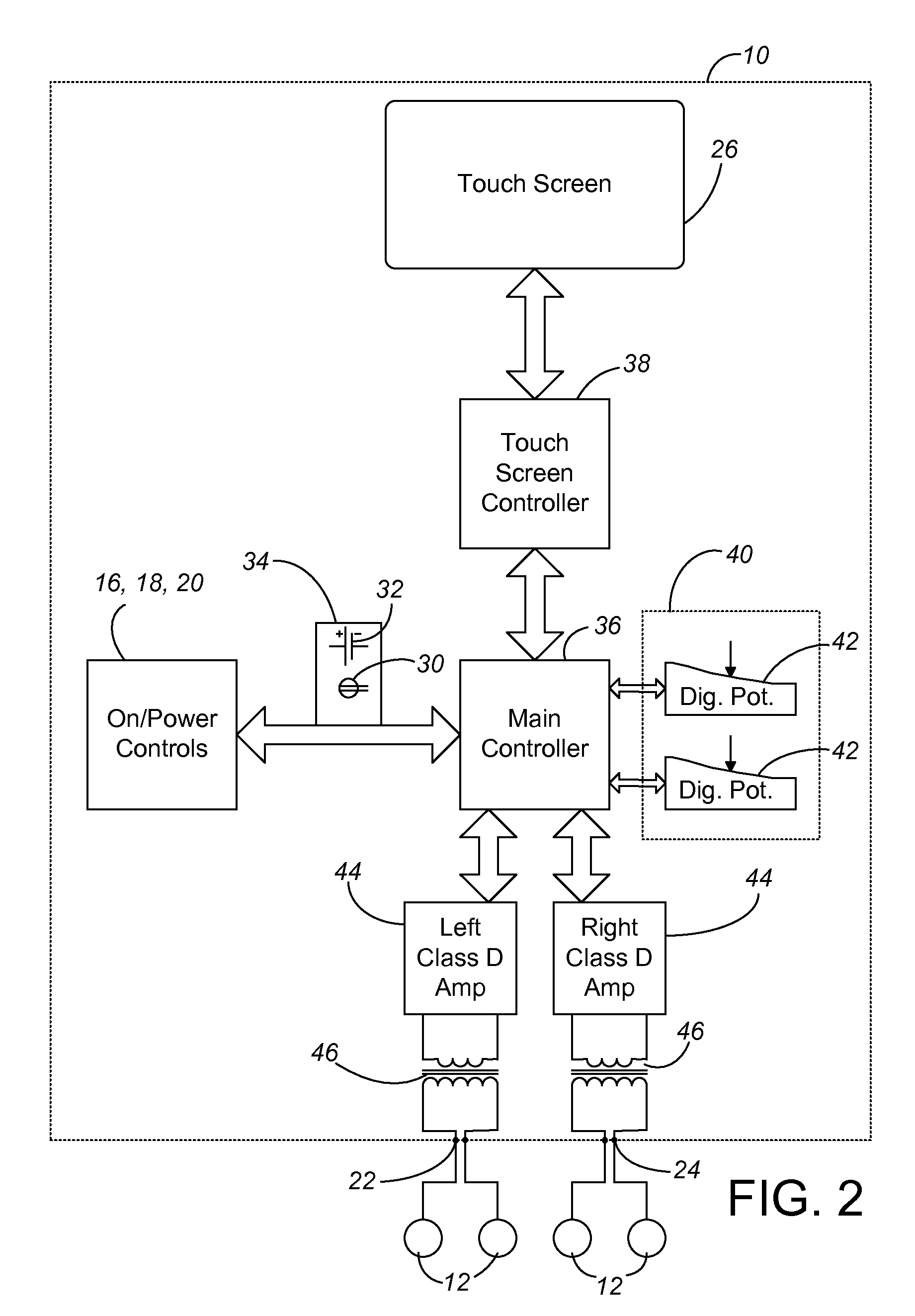
[0023]The present invention involves methods made possible with an electro-therapeutic stimulator 10 providing tunable, reproducible waveform control of a dual periodic-exponential signal form applied to a patient through electrode pads 12. In the preferred form, the electro-therapeutic stimulator 10 has a housing 14 with an on / off switch 16, an output power dial 18, a power reset switch 20, a left output jack 22, a right output jack 24, and a touch / display screen 26. The electro-therapeutic stimulator 10 may be powered either through a standard electrical power plug 30 (120 / 240 volts, 50 / 60 Hz AC input power, shown schematically in FIG. 2), or via a battery 32 (shown schematically in FIG. 2) such as a lithium ion 15 VDC battery. The left and right output jacks 22, 24 each receive a plug 28 for a pair of electrodes 12 (typically one black or negative and the other red or positive) as known in the electro-therapeutic stimulator art. Preferred electrodes 12 are intended to achieve the...


PUM


Abstract

An electro-therapeutic stimulator provides an output signal having a first controllable main pulse periodic-exponential signal and a second background pulse periodic-exponential signal. The main pulse signal is controllable, preferably to a digital numerical value of 1 to 500 pulses per second, to a digital, numerical value of duty cycle, and to a digital numerical value of balance. The signal is produced using a class D amplifier and with a transformer optimized for the background pulse (such as at 10 kHz) rather than for the main pulse. The electro-therapeutic stimulator includes a counter which forces purchasing of durations of signal time for ongoing use of the stimulator, and a challenge code procedure for facilitating additional time purchases.

Description

CROSS-REFERENCE TO RELATED APPLICATION(S)[0001]This application claims priority from Provisional Application No. 61 / 248,694, filed Oct. 5, 2009, entitled ELECTRO-THERAPEUTIC STIMULATION.BACKGROUND OF THE INVENTION[0002]The present invention improves upon the apparatus and methods of U.S. Pat. Nos. 5,107,835 and 5,109,848, both of which are incorporated by reference. The ornamental appearance of one version of practicing the present invention is described in U.S. Pat. No. D603,971, incorporated by reference.[0003]It has long been known that the neurological system operates significantly based on electrical impulses. The neurological system works in two directions, both transmitting feeling sensation and pain to the brain, and in firing muscles responsive to impulses from the brain.[0004]It has also long been known that non-biological sources of electrical stimulation can be used to control certain muscles. For instance, the pacemaker works on this principle. Transcutaneous electrical...

Claims


Application Information

Patent Timeline
IPC IPC(8): A61N1/08A61N1/36
CPCA61N1/36003A61N1/36171A61N1/36021A61N1/36014A61N1/36175A61N1/36031A61N1/36034
Inventor THOMAS, GARY EDWARDTHOMPSON, DENISSCHROEDER, JR., FRANKLIN WILLIARDDEMMA, DONALD ANTHONY
Owner ARP MFG
Why Eureka
Try Eureka