
Intervertebral fixation device

a fixation device and cervical vertebrae technology, applied in the field of intervertebral fixation devices, can solve the problems of not being able to move at all, not being able to match with the physiological curvature of each patient's cervical vertebrae,

Inactive Publication Date: 2011-04-07
YEH AN SHIH
View PDF5 Cites 53 Cited by
  • Summary
  • Abstract
  • Description
  • Claims
  • Application Information

AI Technical Summary

Benefits of technology

[0012]Therefore, it is a primary objective of the present invention to provide an intervertebral fixation device, comprising at least one bending portion disposed on a plate member and provided for flexibly adjusting the curvature of the intervertebral fixation device, such that the intervertebral fixation device is matched with the physiological curvature of each patient's cervical vertebrae to overcome the shortcomings of the conventional intervertebral fixation device having a bump after a surgical operation takes place, and prevent a locking element secured to the conventional intervertebral fixation device from being loosened or fallen off, and avoid taking another surgical operation again.

Problems solved by technology

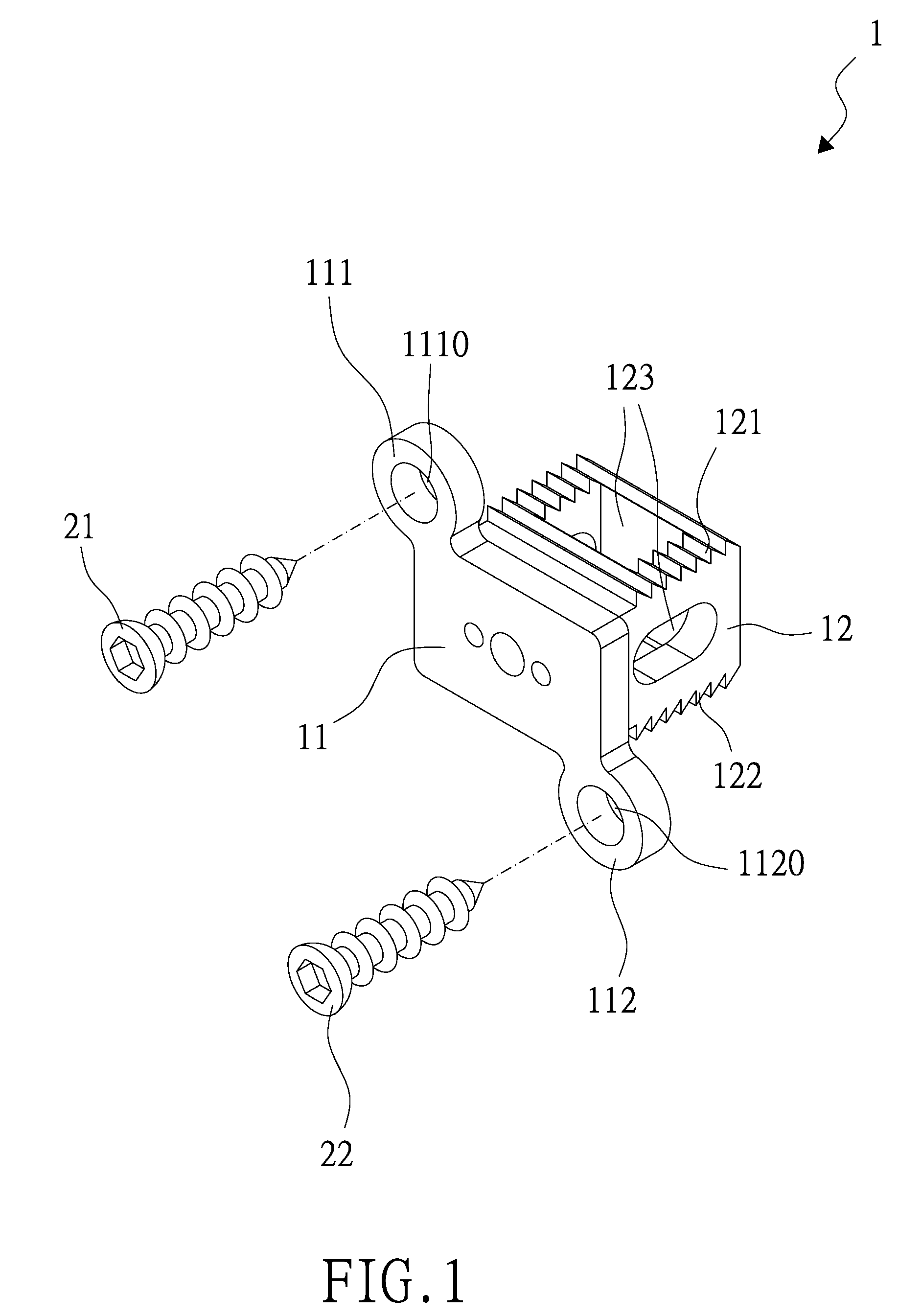
The spinal cord contains spinal nerves and is composed of vertebrae, such that if any of our vertebrae is shifted, then we will be unable to move conveniently or even unable to move at all in a serious case.
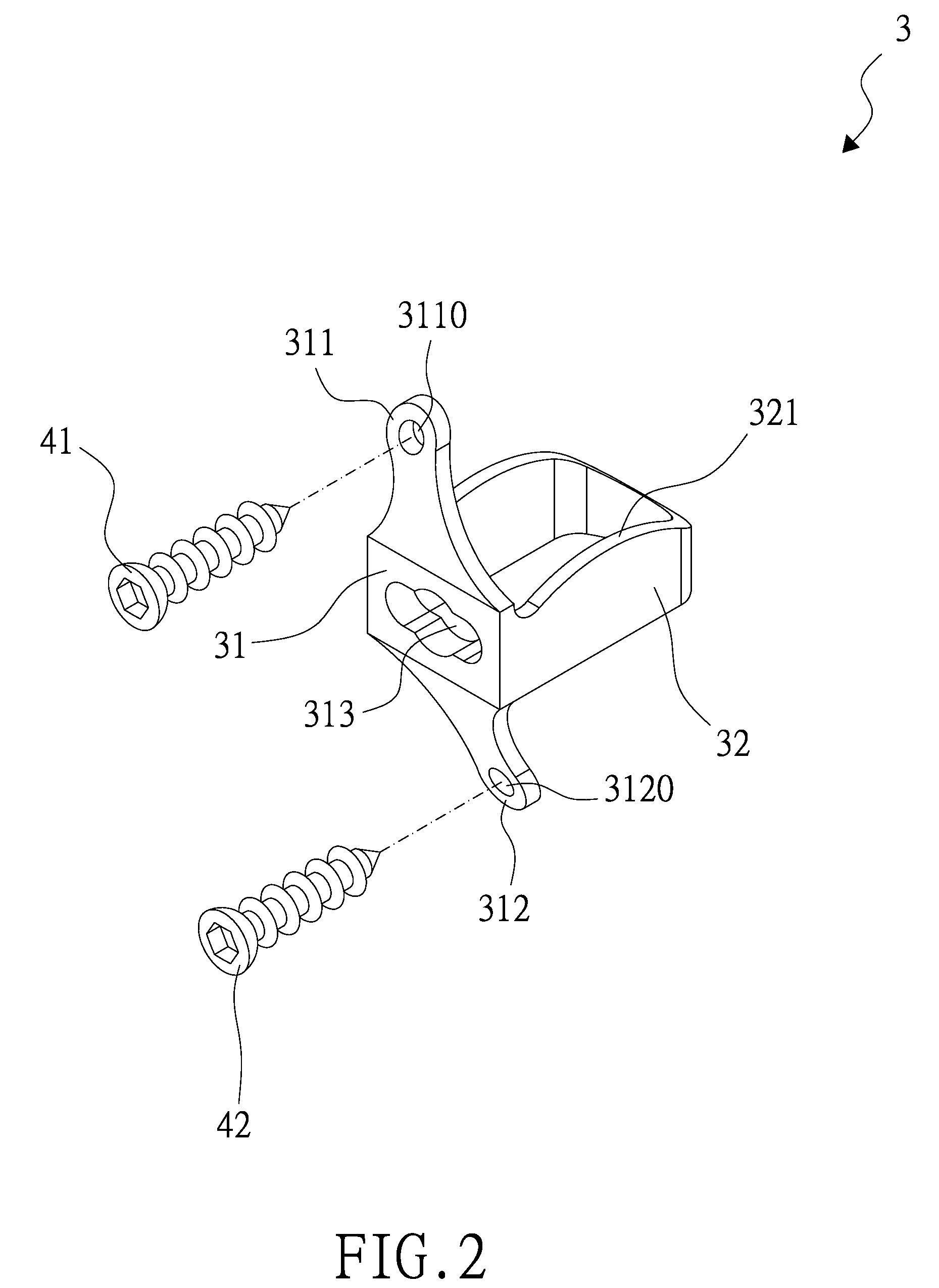
However, the other intervertebral fixation device 3 is made of a metal, so that the elasticity is not as good, and the aslant curvature of the lugs 311, 312 may not be able to match with the physiological curvature of each patient's cervical vertebrae.

Method used


Image

  • Intervertebral fixation device
  • Intervertebral fixation device
  • Intervertebral fixation device

Examples


Embodiment Construction

[0020]To make it easier for our examiner to understand the technical measures and the operating procedure of the present invention, we use preferred embodiments together with the attached drawings for the detailed description of the present invention.

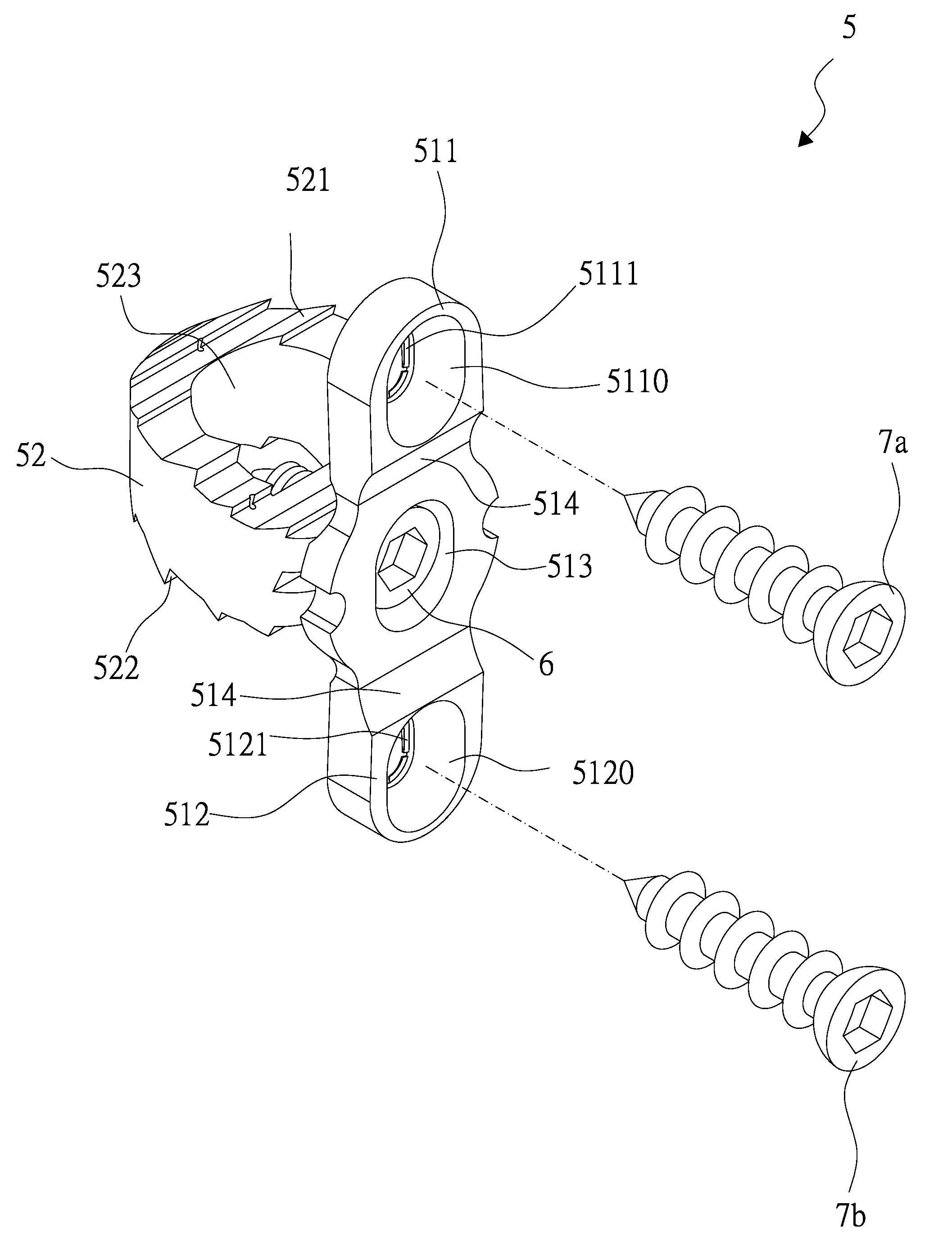
[0021]With reference to FIGS. 3 to 6 for perspective views of a plate member of an intervertebral fixation device 5 and a perspective view of assembling the intervertebral fixation device 5 in accordance with the present invention respectively, the intervertebral fixation device 5 comprises a plate member 51 and a body 52.

[0022]An ear portion 511 is extended upwardly from an end of the plate member 51, and a first hole 5110 is formed at a central position of the ear portion 511, and another ear portion 512 is extended downwardly from another end of the body 51, and a second hole 5120 is formed at a central position of the other ear portion 512, and a plurality of wing plates 5111, 5121 are disposed on a side of the first hole 5110 and t...


PUM


Abstract

This invention discloses an intervertebral fixation device including a plate member, a body, and at least one bending portion disposed on the plate member. The thickness of the bending portion is slightly smaller than the thickness of the plate member and ear portions, such that the bending portion is provided for flexibly adjusting a curvature of the plate member of the intervertebral fixation device, and an ear portion and another ear portion on the plate member can be adjusted flexibly to be attached to the two cervical vertebrae, and the intervertebral fixation device can match with the physiological curvature of each patient's cervical vertebrae, so as to overcome the shortcomings of a conventional intervertebral fixation device having a protrusion after a surgical operation is performed, and prevent a locking element secured to a conventional intervertebral fixation device from being loosened, and avoid another surgical operation of a patient.

Description

BACKGROUND OF THE INVENTION[0001]1. Field of Invention[0002]The present invention relates to an intervertebral fixation device, and more particularly to an intervertebral fixation device having at least one bending portion disposed on a plate member of the intervertebral fixation device, and the thickness of the bending portion is slightly smaller than the thickness of the plate member and ear portions, and the bending portion is provided for flexibly adjusting the curvature of the intervertebral fixation device to fit a physiological curvature of a patient's cervical spine, so as to overcome the shortcomings of conventional intervertebral fixation devices that may cause a bump after a surgery operation takes place, a locking element of the conventional intervertebral fixation devices being loosened or fallen out, and may require a patient to take another surgical operation again.[0003]2. Description of Related Art[0004]Human body is supported by skeleton inside the body, so that mu...

Claims


Application Information

Patent Timeline
IPC IPC(8): A61F2/44A61B17/70
CPCA61B17/70A61B17/7059A61B17/8052A61F2/4465A61F2220/0025A61F2002/30578A61F2002/30604A61F2002/30904A61F2002/4475A61F2002/30507A61F2002/30593
Inventor YEH, AN-SHIH
Owner YEH AN SHIH
Learn More