Eureka AIR delivers breakthrough ideas for toughest innovation challenges, trusted by R&D personnel around the world.

Integral control box, spinner and funnel unit with adjustable legs

a technology which is applied in the field of control box and spinner plate assembly for use with wildlife feeders, can solve the problems of difficult access of varmints to the control plate, and achieve the effect of removing varmint access

Inactive Publication Date: 2011-04-21
ALL SEASONS FEEDERS
View PDF57 Cites 5 Cited by
  • Summary
  • Abstract
  • Description
  • Claims
  • Application Information

AI Technical Summary

Benefits of technology

[0009]It is a more particular object of the present invention to provide for a strong, stable mounting of a control box / spinner assembly to a hopper and further a mounting which is capable of limiting the accessibility of the spinner plate and the feed thereon from varmints, critters, and the like.SUMMARY OF THE INVENTION
[0011]This gap is sufficient for the spinner plate location and operation but also is small enough to prevent access by critters to the spinner plate (which may have feed on it) or the feed opening. The small gaps and the specific dimensions, as well as the geometry of the flat base and flat top to the control box housing, make for difficult access of varmints attempting to reach the control plate.
[0012]A wildlife feeder comprising a hopper having an engagement plate, the engagement plate including a tabular, flat, generally horizontal base and having a feed opening therein; a spinner; and a control box having a control box housing having an upper wall and a motor, the motor with a drive shaft, the spinner mounted to the end of the drive shaft and centered below the feed opening of the base; wherein the upper wall of the control box is aligned below and spaced apart from the base of the engagement plate so as to generally eliminate varmint access thereto.

Problems solved by technology

The small gaps and the specific dimensions, as well as the geometry of the flat base and flat top to the control box housing, make for difficult access of varmints attempting to reach the control plate.

Method used


Image

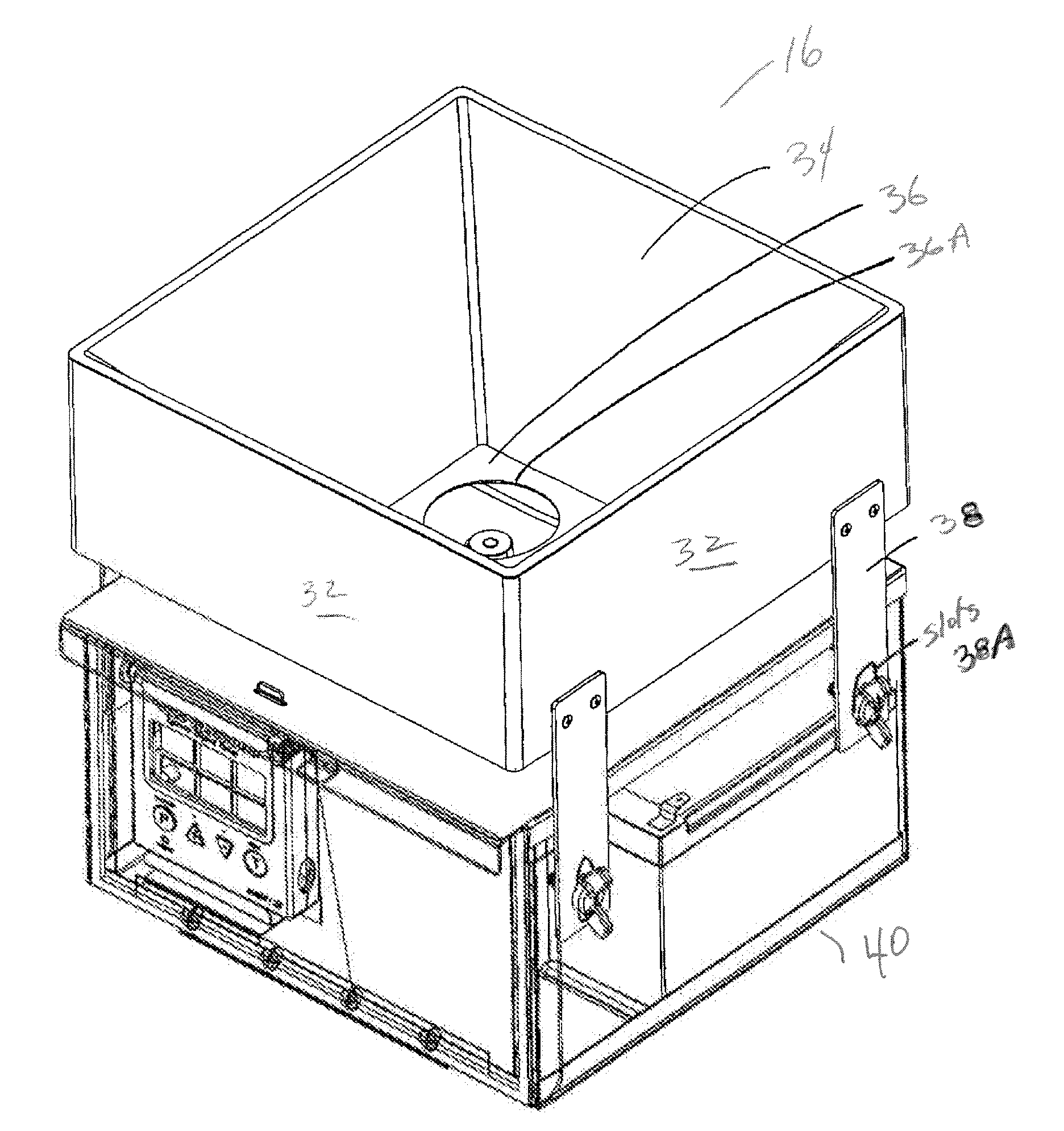
  • Integral control box, spinner and funnel unit with adjustable legs
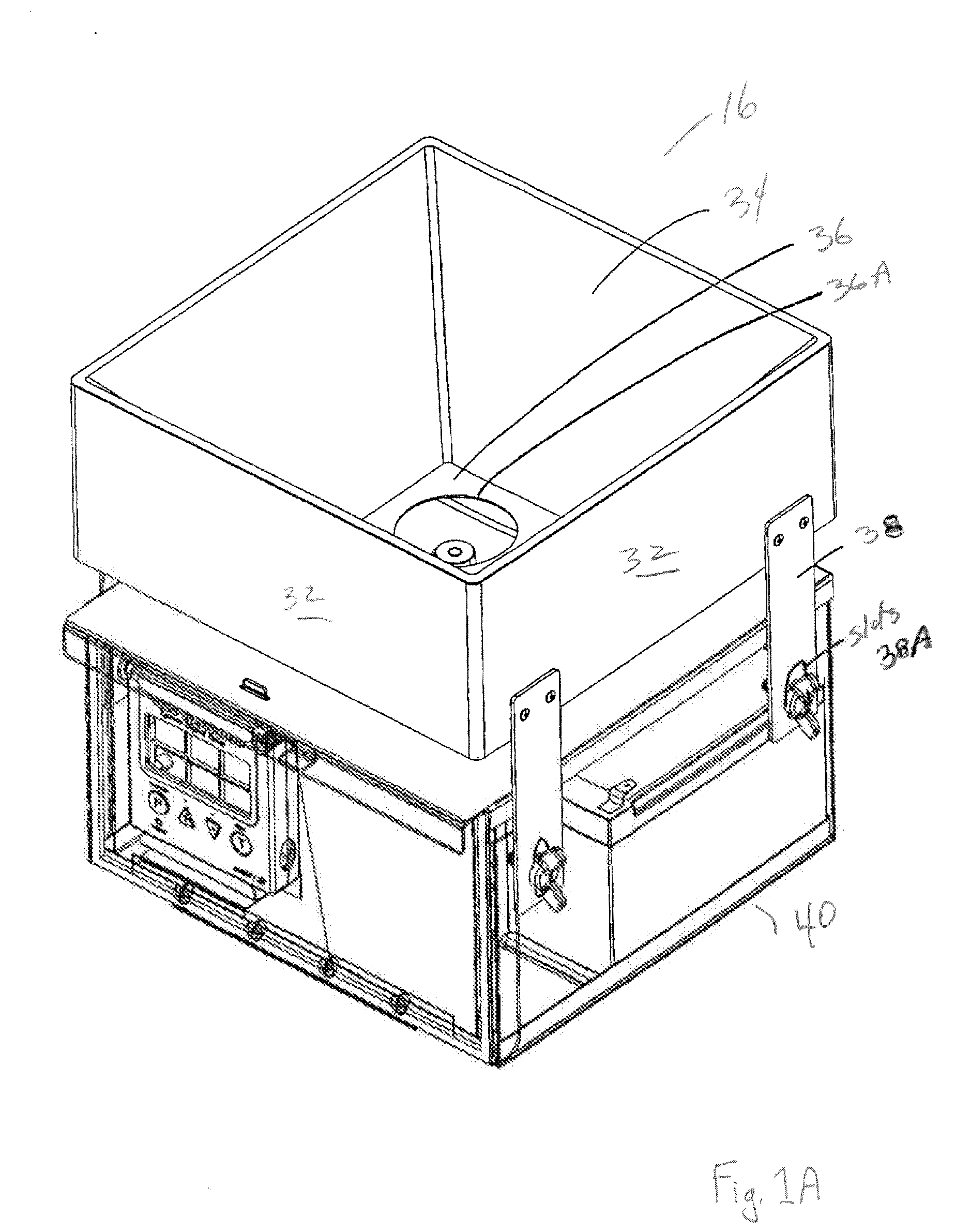
  • Integral control box, spinner and funnel unit with adjustable legs
  • Integral control box, spinner and funnel unit with adjustable legs

Examples


Embodiment Construction

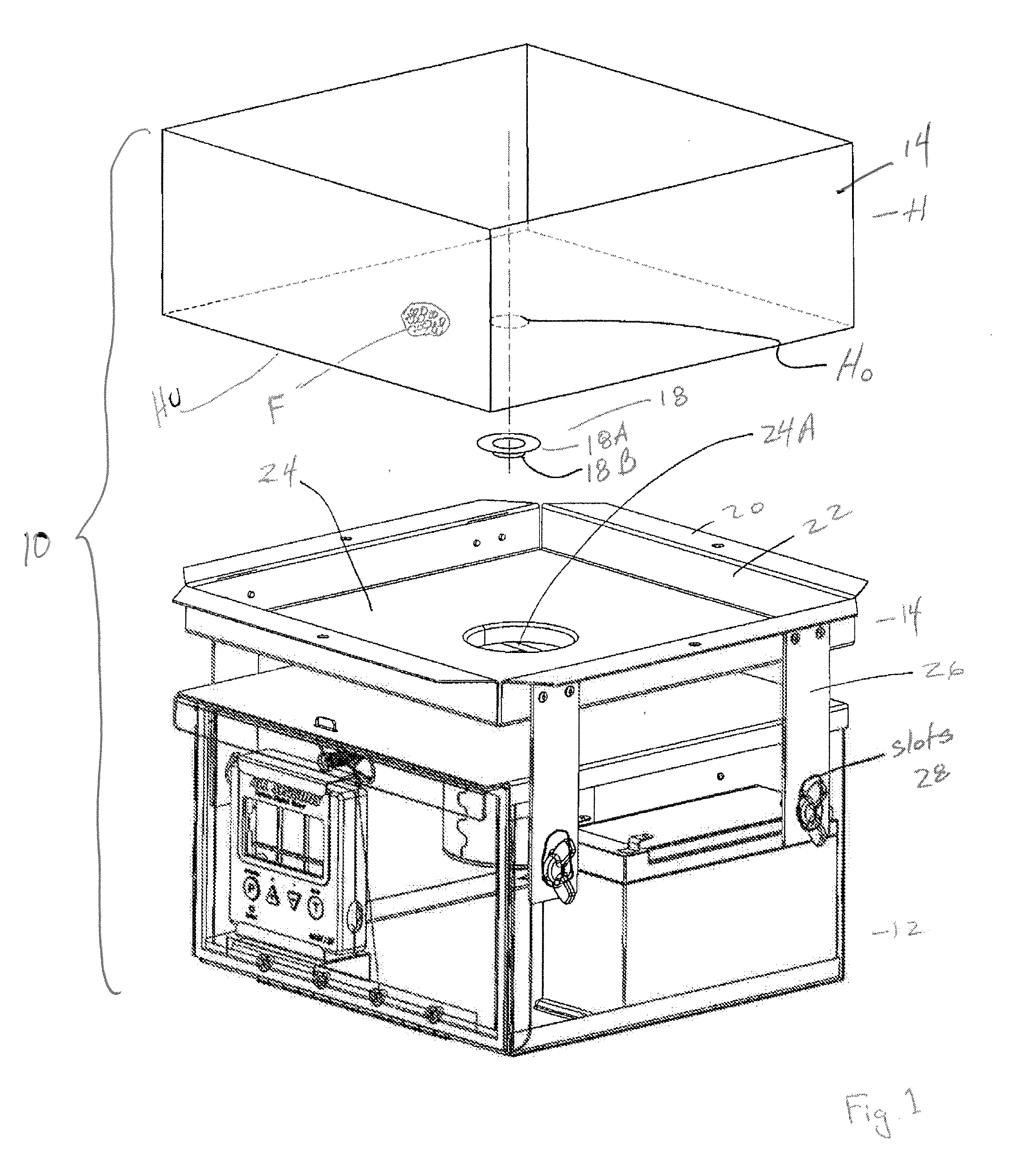
[0026]With reference to the attached Figures, it is seen that Applicant provides a combination unit 10, which combination unit 10 includes a control box / spinner plate assembly 12 (similar in some regards to prior art), which is adjustably engaged to a novel hopper engagement plate 14 / 16. A first embodiment of the hopper engagement plate is identified with the numeral 14 and a second embodiment identified with the numeral 16.

[0027]A funnel 18 may be used, optionally, to engage a bottom opening HO in a hopper H in ways known in the art. Hopper H is seen to contain feed F, typically particulate corn or the like, and hopper may have a bottom wall or underside HU.

[0028]Turning now to hopper engagement plate 14, it is seen that, like hopper engagement plate 16, when engaged to the bottom of a hopper, regardless of the shape of the bottom of the hopper, hopper engagement plate 14 / 16 will have a base that will lay in a horizontal plane and will typically substantially mirror the shape and d...


PUM


Abstract

A wildlife feeder with a control box assembly for engaging a bottom wall of a hopper of a wildlife feeder is provided, the bottom wall having a hopper feed dispensing opening. The hopper is supported on a multiplicity of legs above the ground. The assembly includes a motor with a drive shaft, and a spinner mounted near a removed end of the drive shaft. A control box having a control box housing is provided with an upper wall, the upper wall having an opening to allow the drive shaft to project substantially vertically therethrough. A hopper engagement plate is provided for engaging the bottom wall of the hopper adjacent the hopper feed dispensing opening. The hopper engagement plate has a base with a feed opening therethrough. The hopper engagement plate has walls with a multiplicity of legs depending therefrom. The feed opening of the base is located substantially below the hopper feed dispensing opening.

Description

[0001]This utility patent application claims the benefit of and incorporates herein by reference U.S. Provisional Patent Application Ser. No. 61 / 253,368, filed Oct. 20, 2009; and U.S. Provisional Patent Application Ser. No. 61 / 290,301, filed Dec. 28, 2009.FIELD OF THE INVENTION[0002]Wildlife feeders, more specifically, control boxes and spinner plate assemblies for use with wildlife feeders.BACKGROUND[0003]Integral control box and spinner assemblies are known for use with wildlife feeders. These prior art control box / spinner assemblies are typically designed to depend from the bottom of a leg mounted hopper of a wildlife feeder. The hoppers usually stand at least several feet above the ground on three or four legs. They channel the particulate feed contained therein to an opening, typically centrally located at the bottom of the hopper. Prior art control box / spinner plate assemblies are then typically mounted below the centrally located opening of the hopper on a pair of hopper moun...

Claims


Application Information

Patent Timeline
Patent Type & Authority Applications(United States)
IPC IPC(8): A01K5/02A01K5/00
CPCA01K5/0225A01K5/02
Inventor GATES, BURNELL
Owner ALL SEASONS FEEDERS
Why Eureka
Eureka Blog
Learn More