
Ophthalmologic lens assembly

a technology of ophthalmologic lenses and lenses, applied in the field of optical lenses and ophthalmologic lenses with, can solve the problems of lens lenses that use tir surfaces are also susceptible to tir failure, lenses also suffer from the drawbacks of plastic prisms, and glass prism lenses can be coated with high-performance materials that are not possible to adhere to plastic lenses

Inactive Publication Date: 2011-04-21
OCULAR INSTR
View PDF2 Cites 9 Cited by
  • Summary
  • Abstract
  • Description
  • Claims
  • Application Information

AI Technical Summary

Benefits of technology

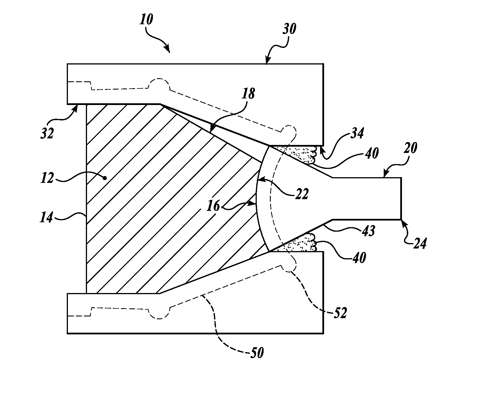
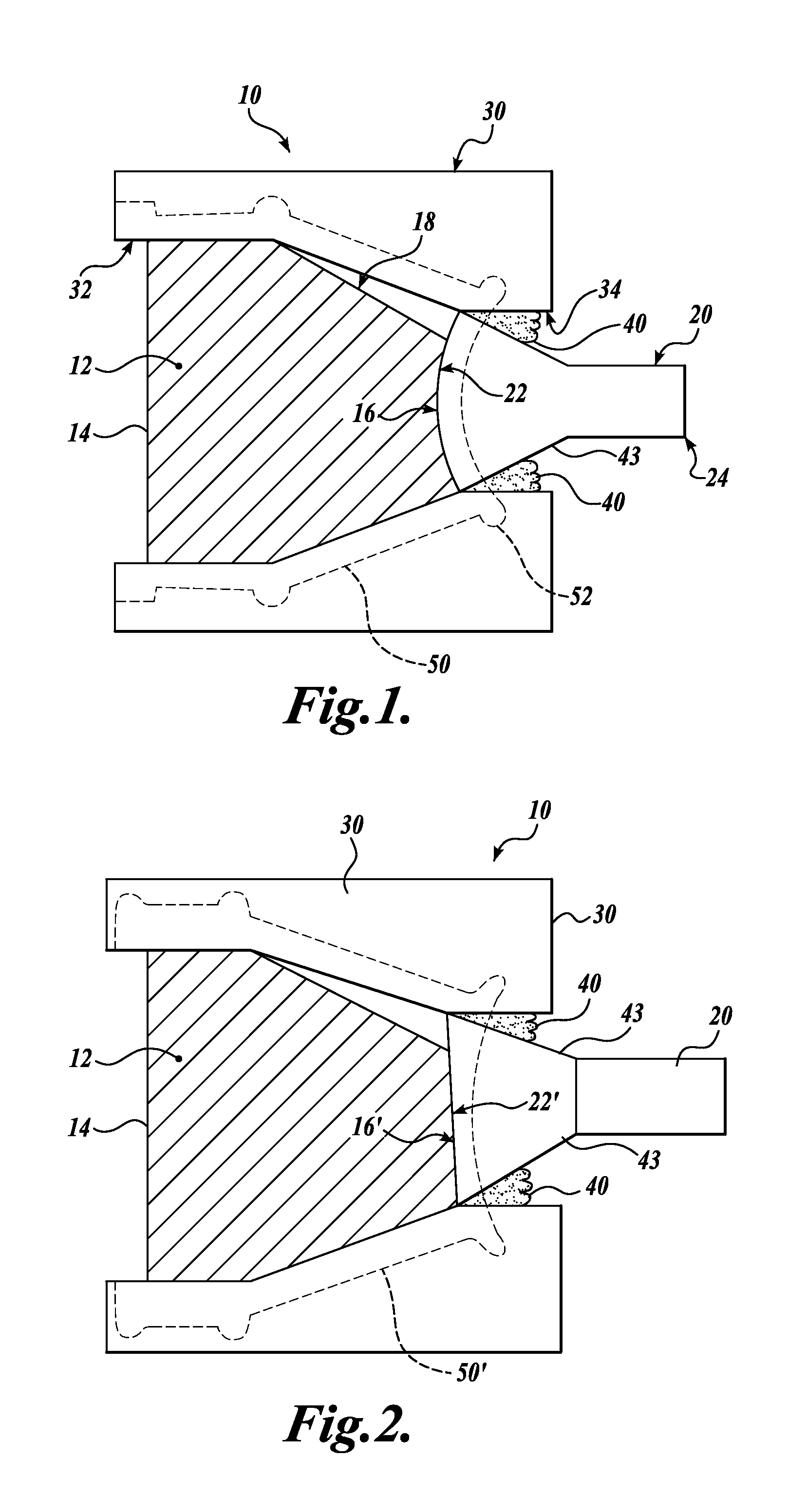
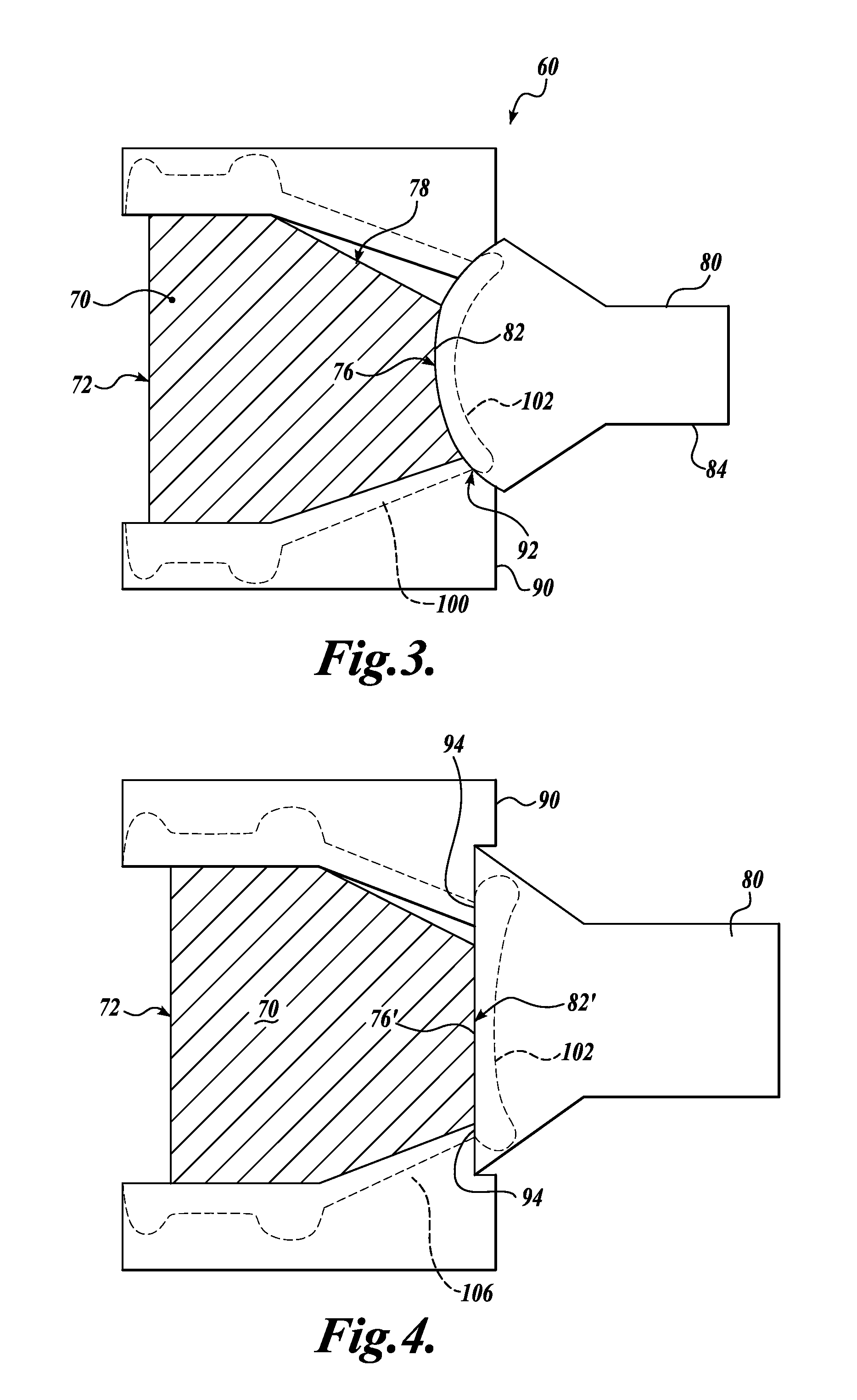
The technology described in this patent is an ophthalmologic lens assembly that includes a glass prism and a meniscus lens bonded together. The assembly is protected and sealed in a housing. The lens assembly can be made by bonding a finished anterior lens surface of a meniscus lens blank to a posterior lens surface of a glass prism, or by securing the meniscus lens blank to a housing blank and then bonding the posterior lens surface of the glass prism to the finished anterior lens surface of the meniscus lens blank. The lens assembly can be designed to improve image quality and provide a better view for ophthalmic procedures.

Problems solved by technology

In addition, glass prism lenses can be coated with high performance materials that are not possible to adhere to plastic lenses due to the high temperatures required to apply the materials.
However any prism that uses TIR surfaces is also susceptible to TIR failure when something touches the exterior of a reflecting surface or the exterior reflecting surface is exposed to a liquid or other substance that changes the index of refraction of the surface.
However such lenses also suffer from the drawbacks associated with plastic prisms.
On the other hand, lens designs with glass prisms are not easily placed in a housing due to difficulties in getting a housing material to adhere to the glass and because of the differing grinding and polishing characteristics of the glass and housing materials.
The minor coating eliminates the possibility of TIR failure but also reduces the brightness the lens.
In addition, a mirror coating can limit the use of the lens assembly.
For example, some mirrored lenses cannot be used with certain types of lasers.

Method used


Image

  • Ophthalmologic lens assembly
  • Ophthalmologic lens assembly
  • Ophthalmologic lens assembly

Examples


Embodiment Construction

[0017]As will be set forth in detail below, the technology described herein relates to an ophthalmologic lens assembly that incorporates a glass prism that may have one or more reflecting surfaces that use TIR. To protect the prism and the reflecting surfaces of the prism, the glass prism is surrounded by a housing, which is secured and sealed to a meniscus lens. In some embodiments, the meniscus lens is made of the same or a similar material as the housing such that the housing and meniscus lens can be bonded together in order to seal the glass prism in the housing.

[0018]As shown in FIG. 1, an ophthalmologic lens assembly 10 includes a glass prism 12 having an anterior lens surface 14 and a posterior lens surface 16. In some embodiments, the glass prism includes one or more reflecting surfaces 18 cut or formed into the glass prism 12 that reflect light by total internal reflection. In one embodiment, the glass prism 12 is made of quartz. However, other optical glasses could be used...


PUM

PropertyMeasurementUnit
total internal reflectionaaaaaaaaaa
diameteraaaaaaaaaa
sharp anglesaaaaaaaaaa

Abstract

An ophthalmologic lens assembly includes a glass prism bonded to a meniscus lens at a posterior end of the glass prism. The glass prism is surrounded by a housing that is bonded to the meniscus lens. In one embodiment, the housing and a meniscus lens blank are processed by grinding and polishing the housing and meniscus lens blank together to form a posterior lens surface of a meniscus contact lens. In other embodiment, only the meniscus lens blank is processed by grinding and polishing to form a posterior lens surface of a meniscus contact lens.

Description

FIELD OF THE INVENTION[0001]The technology disclosed herein relates generally to optical lenses and to ophthalmologic lenses with glass prisms in particular.BACKGROUND[0002]To examine and treat different areas of the eye, ophthalmologists and optometrists often use specialized ophthalmologic lenses to view remote areas of the eyeball. Such lenses may include prisms having reflecting surfaces thereon that allow the user to view areas at sharp angles with respect to the front of the eye.[0003]With most ophthalmologic lenses, there are distinct advantages to having a prism made of a glass material rather than an optical plastic. For example, some glasses have lower dispersion and / or higher transmission characteristics than plastics. In addition, glass prism lenses can be coated with high performance materials that are not possible to adhere to plastic lenses due to the high temperatures required to apply the materials.[0004]To maximize the brightness of a prism, it is known to design t...

Claims


Application Information

Patent Timeline
Patent Type & Authority Applications(United States)
IPC IPC(8): A61B3/10B29C65/42B29C65/54
CPCG02B17/0856A61B3/125
Inventor GRAHAM, RAYMOND D.HARRINGTON, PETER G.
Owner OCULAR INSTR
Learn More