
Method for programming foot pedal settings and controlling performance through foot pedal variation

a foot pedal and variable technology, applied in the field of foot pedal operation control for surgical apparatuses, can solve problems such as no common way to program settings

Active Publication Date: 2011-04-21
JOHNSON & JOHNSON SURGICAL VISION INC
View PDF114 Cites 76 Cited by
  • Summary
  • Abstract
  • Description
  • Claims
  • Application Information

AI Technical Summary

Benefits of technology

[0011]The present invention pertains to a method for programming one or more foot pedal settings, comprising: (1) selecting a switch or a directional movement of a treadle located on a foot pedal; (2) displaying one or more programming options for the selected switch or directional movement of the treadle on a display; (3) toggling through the one or more programming options, wherein the toggling is performed by moving the treadle; and (4) selecting one of the programming options available for the selected switch or directional movement of the treadle. The selecting may be performed by one selected from the group consisting of clicking an icon on the display, pressing a switch on the foot pedal, moving the treadle, voicing a command, and combinations thereof. The one or more programming options is selected from the group consisting of irrigation, aspiration, ultrasonic power, vitrectomy, bottle height, pump speed, pump type, flow rate, and vacuum level. The present invention also pertains to selecting a second switch or second directional movement of the treadle and deactivating or locking the second switch or second directional movement.

Problems solved by technology

As may be expected, there are many types of foot pedals, but no common way to program the settings that are available for each type.

Method used


Image

  • Method for programming foot pedal settings and controlling performance through foot pedal variation
  • Method for programming foot pedal settings and controlling performance through foot pedal variation
  • Method for programming foot pedal settings and controlling performance through foot pedal variation

Examples


Embodiment Construction

[0026]Reference will now be made in detail to embodiments of the invention, examples of which are illustrated in the accompanying drawings. While the invention will be described in conjunction with the embodiments, it will be understood that they are not intended to limit the invention to those embodiments. On the contrary, the invention is intended to cover alternatives, modifications, and equivalents, which may be included within the spirit and scope of the invention as defined by the appended claims.

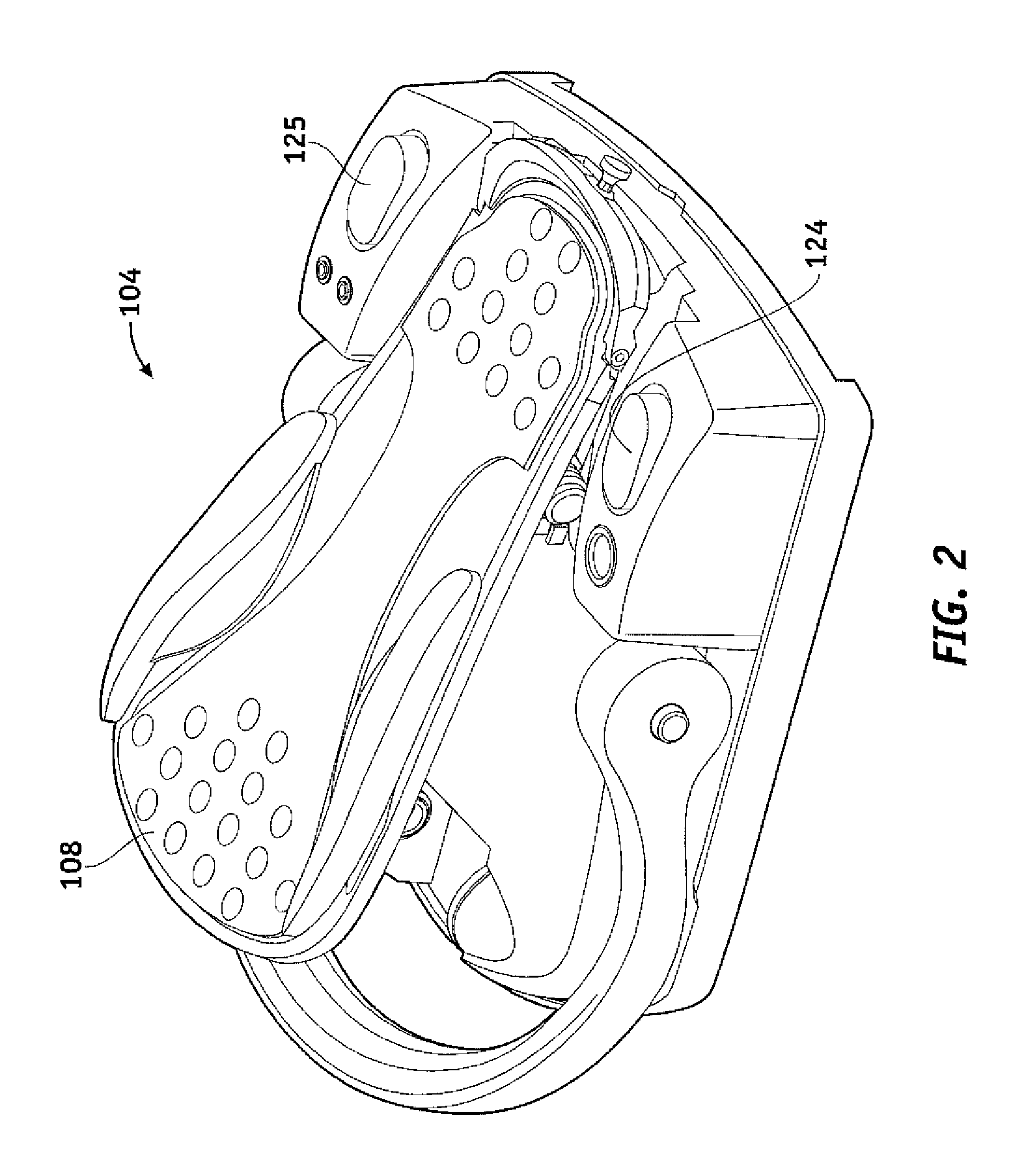
[0027]The present invention may be used with any foot pedal known in the art for use with medical apparatuses, including dual linear foot pedals and single linear foot pedals.

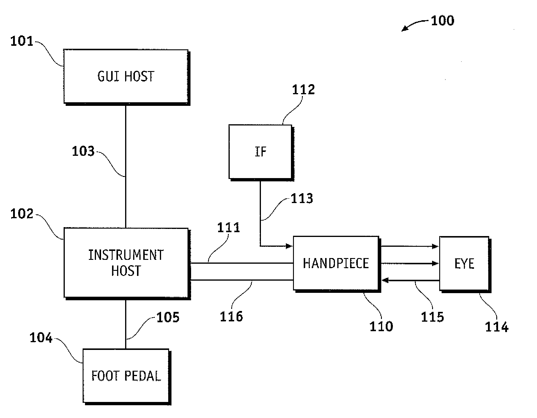
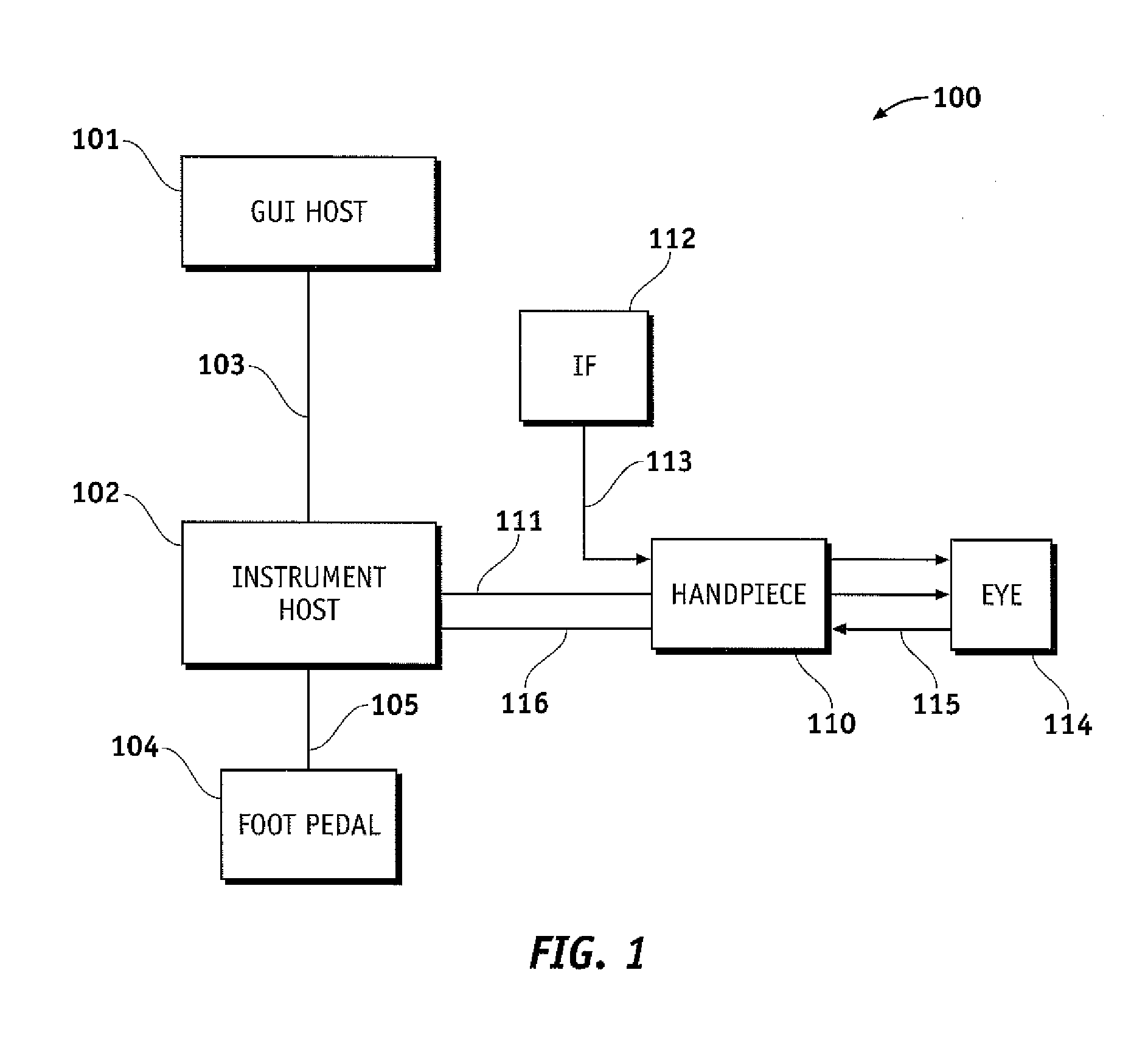
[0028]FIG. 1 illustrates an exemplary phacoemulsification / vitrectomy system 100 in a functional block diagram to show the components and interfaces for a safety critical medical instrument system that may be employed in accordance with an aspect of the present invention. A serial communication cable 103 connects ...


PUM


Abstract

The present invention pertains to programming a foot pedal and switches located therewith that is used with a medical device and / or medical device system. A user may select any switch or directional movement available on the foot pedal for programming by activating the switch and / or moving a treadle located on the foot pedal or by selecting a foot pedal feature on a display. The programming options available for the selected switch or directional movement are displayed on the display screen. Using the foot pedal, the display screen, voice command or combinations thereof, the user can navigate through different options to select one or more options and confirm the chosen option(s) for the particular switch or directional movement. The control and feel of the movement of the treadle and / or switch provides the user with the ability to program custom settings that suit the user's foot position(s) and / or particular style of surgery.

Description

TECHNICAL FIELD OF THE INVENTION[0001]The present invention relates generally to medical apparatuses; more particularly, to foot-operated controls for surgical apparatuses. Numerous types of apparatuses include as part of the apparatus, a hand-held medical implement or tool. Operation of the tool requires control of various operating settings or functions.BACKGROUND OF THE INVENTION[0002]Ophthalmic surgical apparatuses such as a phacoemulsification apparatus typically include operating controls for regulating settings or functions of the apparatus. Such phacoemulsification apparatus is particularly directed for surgically removing the natural, crystalline lenses from cataractic eyes prior to the insertion of an artificial intraocular lens.[0003]Such apparatus typically includes a control cabinet, power supply, one or more pumps as well as associated electronic hardware for operating a multifunction handheld surgical implement in order to sonically emulsify eye tissue, irrigate the e...

Claims


Application Information

Patent Timeline
Patent Type & Authority Applications(United States)
IPC IPC(8): A61B17/20A61B17/00G05G1/30G05B19/42
CPCA61B17/00A61B2017/00199A61B2017/00203A61B2017/00225Y10T74/20528A61B2017/00977A61B2019/448A61F9/00745G05G1/445A61B2017/00973
Inventor WONG, WAYNE S.CLAUS, MICHAEL J.HUNTER, TIMOTHYHAJISHAH, ABRAHAMLINKS, JEREMY T.
Owner JOHNSON & JOHNSON SURGICAL VISION INC
Learn More