Systems and methods for complex event processing based on a hierarchical arrangement of complex event processing engines

Inactive Publication Date: 2011-04-21
CERTUSVIEW TECH LLC
View PDF104 Cites 121 Cited by
  • Summary
  • Abstract
  • Description
  • Claims
  • Application Information

AI Technical Summary

Benefits of technology

[0020]In particular, as discussed below in greater detail, the techniques discussed herein for enabling communication amongst different CEP engines in different geographic locations may provide benefits when used in connection with dispatching and managing field service technicians and generally managing a fleet of vehicles. For example, a CEP engine may be situated in multiple vehicles in a fleet, and respective vehicle-based CEP engines may in some instances communicate with each other. Furthermore, a given vehicle-based CEP engine may communicate with one or more mobile devices carried by a supervisor or dispatcher (e.g., a smart phone, tablet computer, or laptop computer, which itself may be executing a CEP engine), and / or may communicate with one or more office-based CEP engines (e.g., a main office or “central” CEP engine) to provide indications of “vehicle-related events” detected at the vehicle. A vehicle-based CEP engine also may receive indications of events from other vehicles, from a CEP engine executing on a mobile device of a supervisor and / or dispatcher CEP, and / or a central CEP engine. In another aspect, a CEP engine in such a system receiving input streams from multiple different vehicles (which input streams themselves may include vehicle-related events) may apply queries to the multiple input streams to determine various “fleet-related events” (e.g., relating to two or more of the vehicles of the fleet).

Problems solved by technology

In addition, unlike conventional rules-based processing systems, CEP engines employ “windows” for complex event detection.

Method used


Image

  • Systems and methods for complex event processing based on a hierarchical arrangement of complex event processing engines
  • Systems and methods for complex event processing based on a hierarchical arrangement of complex event processing engines
  • Systems and methods for complex event processing based on a hierarchical arrangement of complex event processing engines

Examples


Embodiment Construction

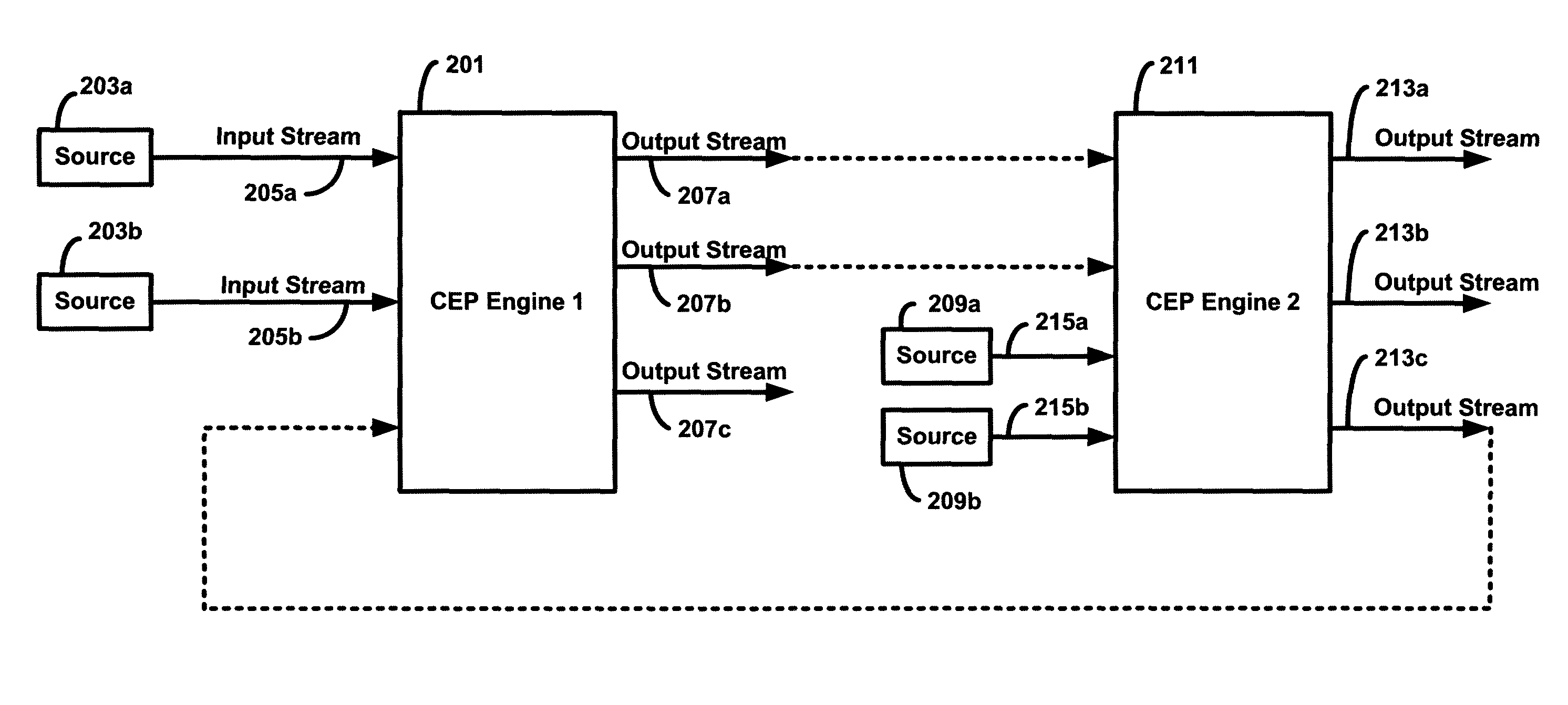
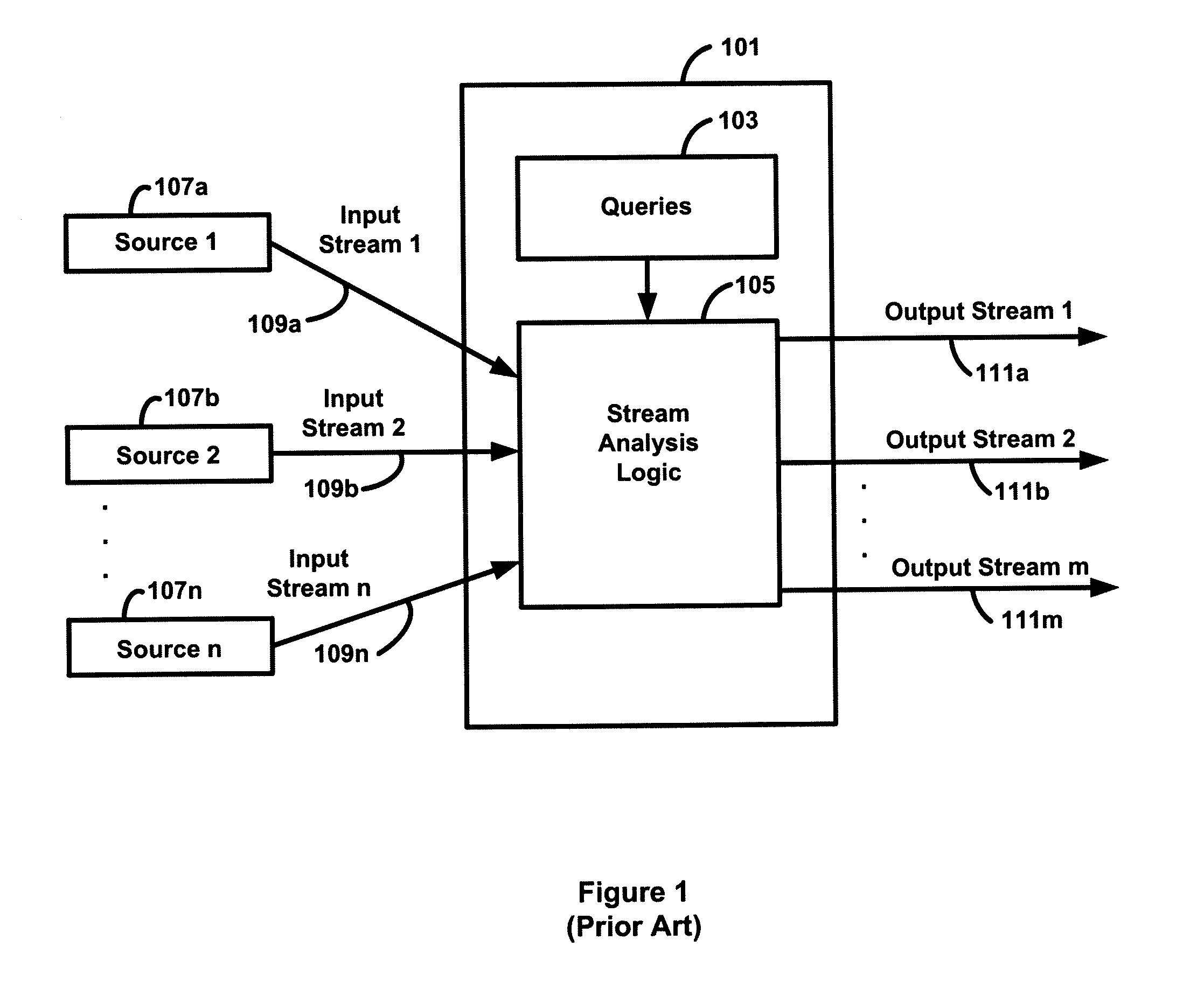
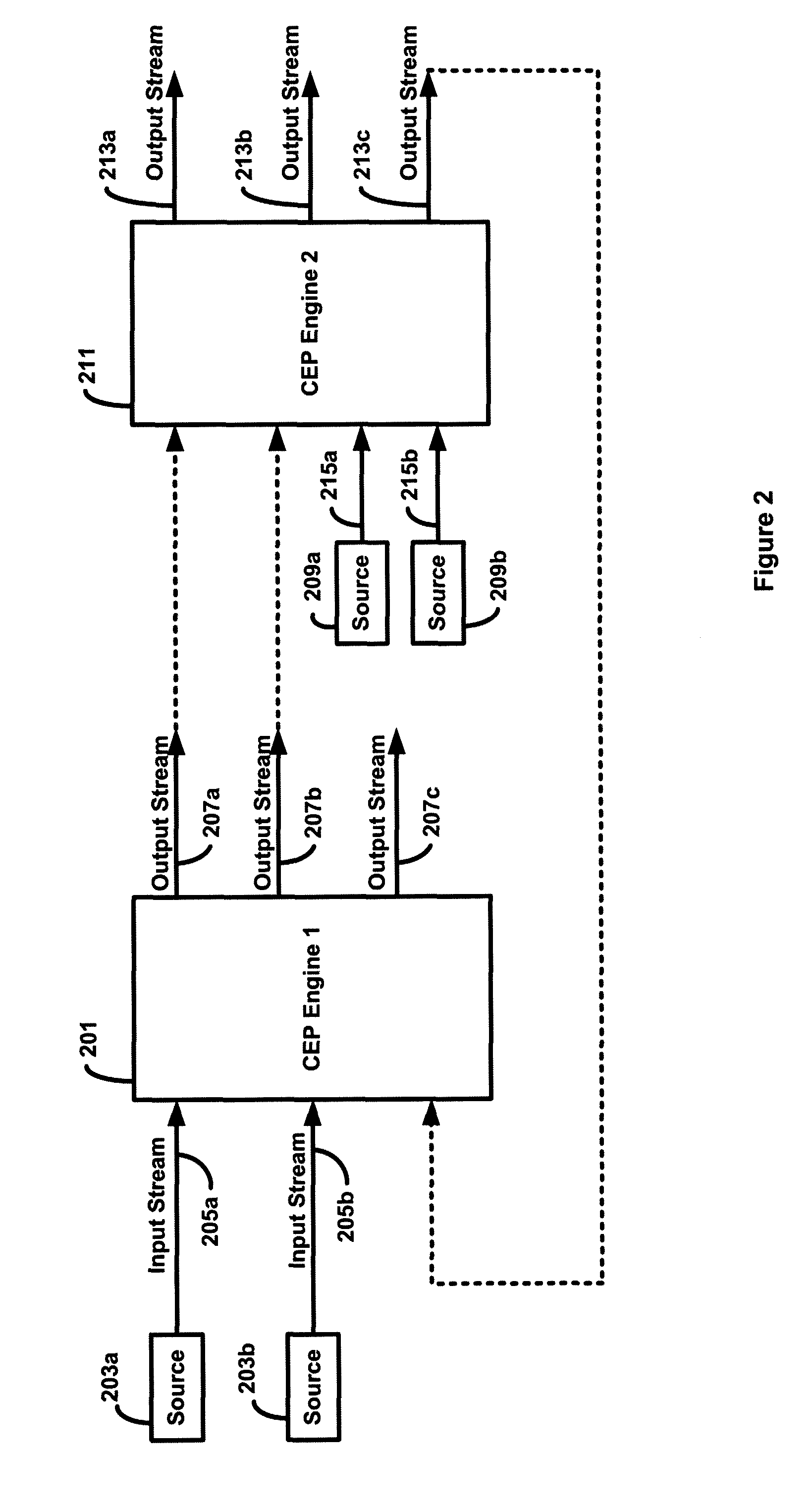
[0060]Following below are more detailed descriptions of various concepts related to, and embodiments of, inventive systems, methods and apparatus for complex event processing. It should be appreciated that various concepts introduced above and discussed in greater detail below may be implemented in any of numerous ways, as the disclosed concepts are not limited to any particular manner of implementation. Examples of specific implementations and applications are provided primarily for illustrative purposes. Although particular examples are discussed herein relating to field service operations and vehicle fleet management, it should be readily appreciated that the concepts disclosed herein are not limited to these exemplary applications.

[0061]A CEP engine may receive data published onto one or more input streams from a plurality of local sensors in the environment of the CEP engine. The inventors have appreciated that, in some situations, it may be desirable for a CEP engine to have a...


PUM


Abstract

A system comprising a plurality of complex event processing engines including a first complex event processing engine set at a first tier and a second complex event processing engine set at a second tier. Each of the plurality of complex event processing engines executes on at least one hardware computer processor. The plurality of complex event processing engines are configured such that at least one complex event processing engine in the second set communicates with only some of the other complex event processing engines in the second set. The plurality of complex event processing engines further are configured such that at least one complex event processing engine in the first set communicates with each complex event processing engine in the second set.

Description

CROSS-REFERENCES TO RELATED APPLICATIONS[0001]The present application claims a priority benefit, under 35 U.S.C. 120, as a continuation (CON) of U.S. non-provisional application Ser. No. 12 / 853,371, filed Aug. 10, 2010, entitled “Systems and Methods for Complex Event Processing of Vehicle Information and Image Information Relating to a Vehicle.”[0002]Ser. No. 12 / 853,371 claims a priority benefit, under 35 U.S.C. §119(a), to Canadian application serial no. 2,712,576, entitled “Systems and Methods for Complex Event Processing of Vehicle-related Information,” filed on Aug. 9, 2010.[0003]Ser. No. 12 / 853,371 claims a priority benefit, under 35 U.S.C. §119(e), to U.S. Provisional Patent Application No. 61 / 232,902, entitled “Systems And Methods For Complex Event Processing,” filed on Aug. 11, 2009.[0004]Ser. No. 12 / 853,371 claims a priority benefit, under 35 U.S.C. §119(e), to U.S. Provisional Patent Application No. 61 / 238,530, entitled “Systems And Methods For Complex Event Processing,” f...

Claims


Application Information

Patent Timeline
Patent Type & Authority Applications(United States)
IPC IPC(8): G06Q10/00G06F19/00
CPCG06Q10/0631H04L67/12G06Q10/087G06Q10/06311
Inventor NIELSEN, STEVENCHAMBERS, CURTISFARR, JEFFREY
Owner CERTUSVIEW TECH LLC
Why Eureka
Try Eureka