Power button assembly and electronic device using the same

Inactive Publication Date: 2011-04-28
HONG FU JIN PRECISION IND (SHENZHEN) CO LTD +1
View PDF2 Cites 6 Cited by
  • Summary
  • Abstract
  • Description
  • Claims
  • Application Information

AI Technical Summary

Problems solved by technology

During assembly, the elastic member and the push button require manual positioning, which can be difficult to accurately achieve.
Over time, the elastic member may

Method used


Image

  • Power button assembly and electronic device using the same
  • Power button assembly and electronic device using the same
  • Power button assembly and electronic device using the same

Examples


Embodiment Construction

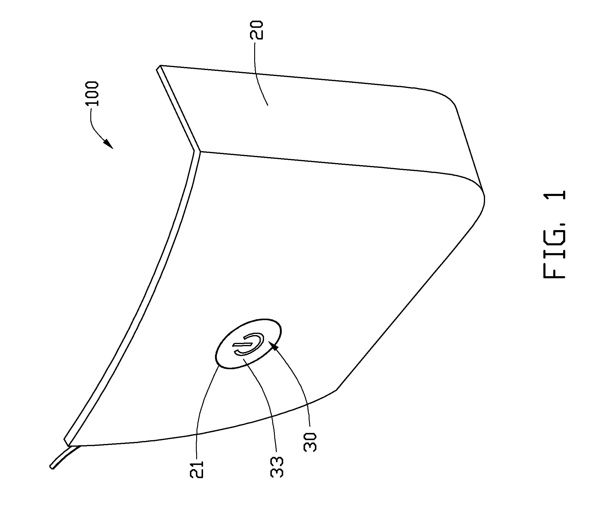
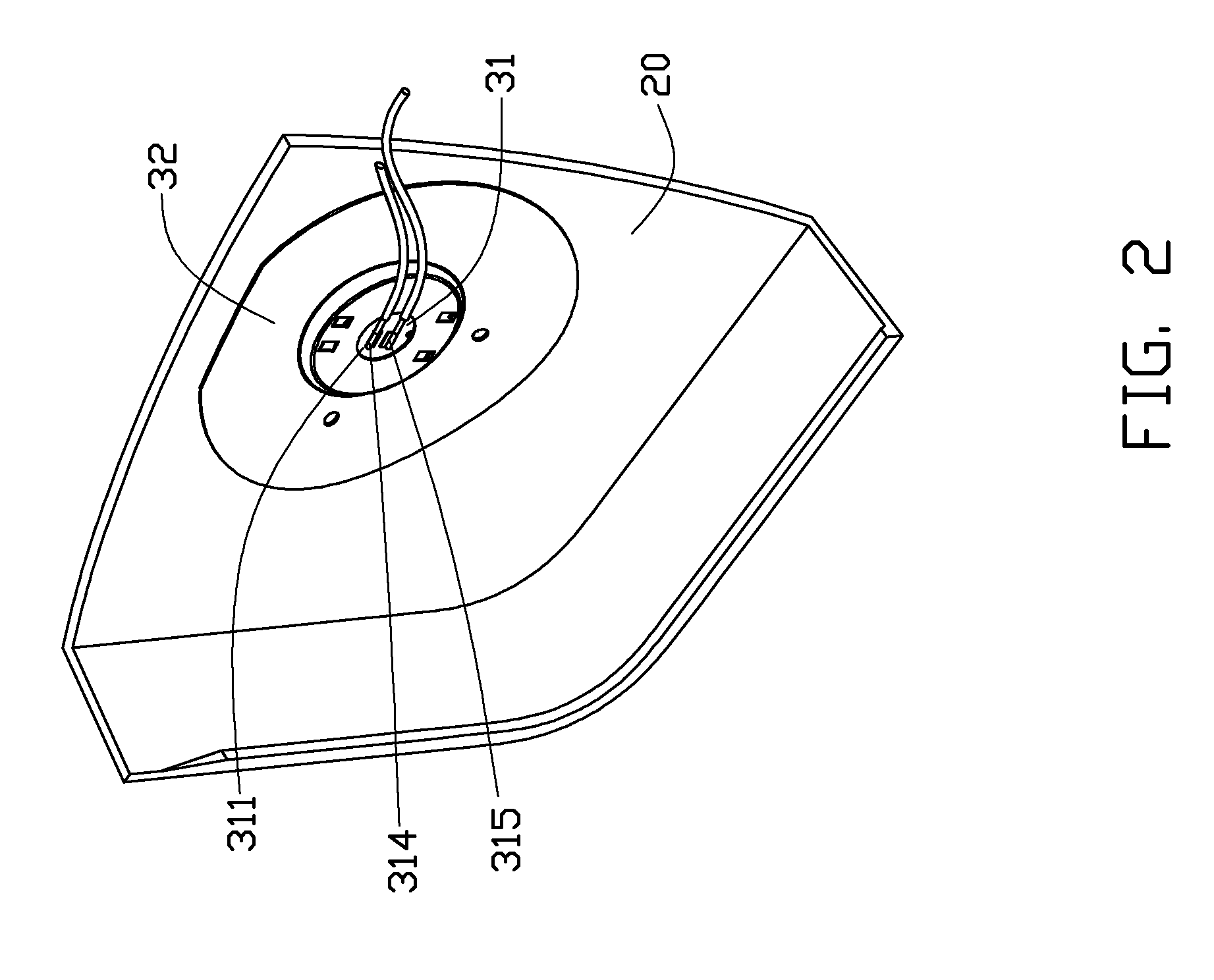
[0012]Referring to FIGS. 1 and 2, an embodiment of an electronic device 100 includes a housing 20 and a power button assembly 30. The housing 20 defines an assembly hole 21 therein. The electronic device 100 may be a notebook, a desktop computer, a liquid crystal display or other electronic device capable of employing the power button assembly 30.

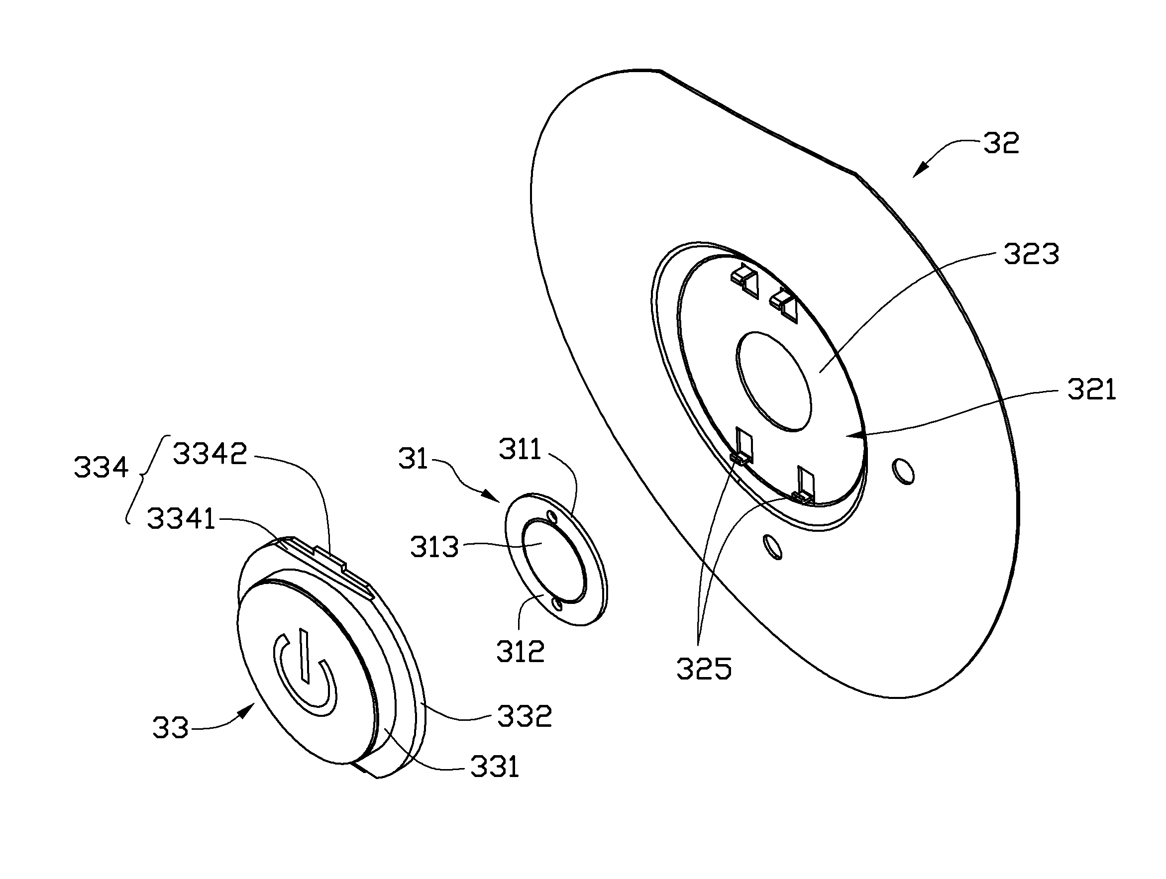
[0013]Referring also to FIGS. 3 and 4, the power button assembly 30 includes a printed circuit board 31, a support plate 32 engaging the printed circuit board 31, and a push button 33.

[0014]The printed circuit board 31 includes a first surface 311 and a second surface 312 opposite to the first surface 311. A switch (not labeled) is positioned on the first surface 311. A dome 313 is positioned on the second surface 312 corresponding to the switch to activate the switch. The switch includes a first electric terminal 314 and a second electric terminal 315 adjacent to the first electric terminal 314. The dome 313 is adjacent to the ends of the ...


PUM


Abstract

A power button assembly includes a printed circuit board having a first surface and a second surface opposite to the first surface, a switch positioned on the first surface, a dome positioned on the second surface corresponding to the switch, a push button resiliently abutted by the dome. One can depress the push button towards the dome, which then capable of depressing the dome to activate the switch. A support plate is engaged with the printed circuit board. One of the support plate and the push button includes two pairs of hook portions, and the other includes two latching portions for engaging with the two pairs of hook portions.

Description

CROSS-REFERENCE TO RELATED APPLICATION[0001]This application is related to a co-pending U.S. patent application Ser. No. 12 / 641,611, file on Dec. 12, 2009, and entitled “POWER BUTTON ASSEMBLY AND ELECTRONIC DEVICE USING THE SAME”. The inventor of the co-pending application is Dai Bin. The co-pending application has the same assignee as the present application. The Specification and Drawings of the co-pending application is incorporated herein by reference.BACKGROUND[0002]1. Technical Field[0003]The present disclosure relates to a power button assembly and an electronic device using the power button assembly.[0004]2. Description of the Related Art[0005]An electronic device is often provided with a power button assembly to turn a power supply on or off. A commonly used power button assembly includes a plurality of components such as a printed circuit board (PCB), a support plate, a push button, and an elastic member positioned between the push button and the PCB to generate an elastic...

Claims


Application Information

Patent Timeline
IPC IPC(8): H01H13/02
CPCH01H13/52H01H13/705H01H2231/002H01H2223/026H01H2223/058H01H2223/014
Inventor DAI, BIN
Owner HONG FU JIN PRECISION IND (SHENZHEN) CO LTD
Why Eureka
Try Eureka