
Method and apparatus for maxillo-mandibular fixation

a technology for mandibular fixation and maxilla, which is applied in the field of method and apparatus for maxilla mandibular fixation, can solve the problems of presenting a real risk of needle sticks and gloves, a fairly elaborate wiring scheme which can only be released with wire cutters, and a very time-consuming and laborious wiring techniqu

Inactive Publication Date: 2011-04-28
STUPAK HOWARD D
View PDF9 Cites 9 Cited by
  • Summary
  • Abstract
  • Description
  • Claims
  • Application Information

AI Technical Summary

Problems solved by technology

However, this wiring technique can be very time-consuming, tedious, and dangerous to surgeons, presenting a real risk of needle sticks and torn gloves.
Moreover, it results in a fairly elaborate wiring scheme which can only be released with wire cutters.
For this reason, the technique poses a real risk of asphyxiation if a patient or care taker is unable to free the jaws in time.
There is also a significant risk that a patient will aspirate cut wire either during an emergency release or during the routine installation or removal of the wires.
However, while this technique is faster, there is risk of injury to the toothroots, which would result in tooth death.
The level of force required to drive screws into cortical bone, either with a pilot hole or without, is considerable, resulting in a relatively difficult and uncomfortable procedure for the patient.
The screws must be placed using instruments such as drills, punches, screw drivers, etc., and many of these instruments are difficult to use within the confines of the mouth, restricting the available angles of approach.
The screws can complicate the repair of jaw fractures.
Moreover, the technique results in a less stable fixation than arch bar wiring MMF because the points of fixation on the respective jaws are significantly further apart from one another, permitting play in the wires, especially if stretched over time.
Additionally, the risk of aspiration with wire-cutter failure remains.
Thus, the traditional methods of immobilizing jaws in dental occlusion for fracture repair have substantial drawbacks.
However, those of skill in this art continue to use these methods despite their drawbacks because the conventional wisdom teaches that only the teeth in aggregate and the cortical bone of the jaw permit fixation that is strong enough to resist the jaw muscles.
The interdental tissues have always been considered too weak to use for this purpose.

Method used


Image

  • Method and apparatus for maxillo-mandibular fixation
  • Method and apparatus for maxillo-mandibular fixation
  • Method and apparatus for maxillo-mandibular fixation

Examples


Embodiment Construction

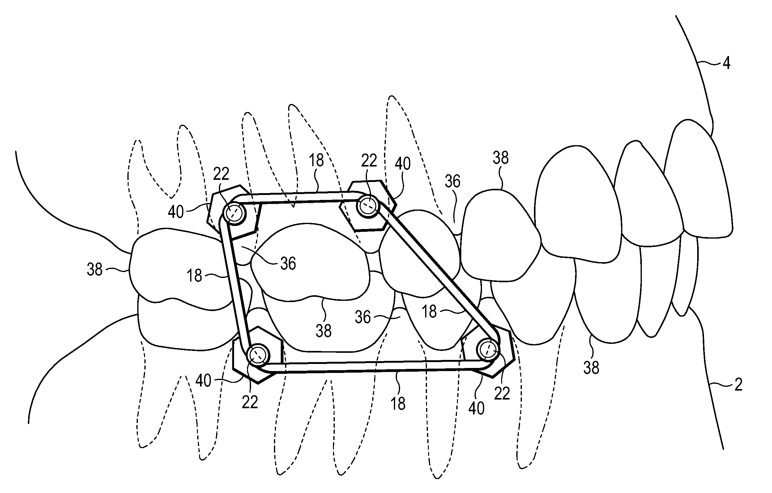
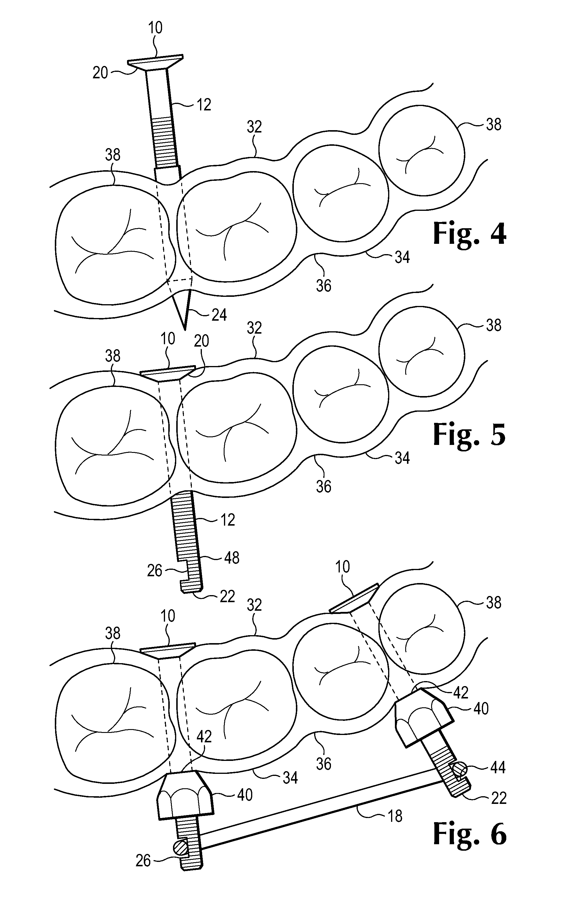
[0019]Mandibular and maxillary bones are made of hard, dense cortical bone into which tooth roots extend and interdental tissue between the teeth themselves. The interdental spaces consist of gingival mucosa and soft tissue and the edge of the alveolar bone, which is spongy and not particularly dense or strong. This interdental tissue has not generally been considered by those of ordinary skill in the art as being strong enough to provide enough fixation strength to accomplish MMF. However, the inventor has discovered and discloses herein methods and apparatus which permit the interdental space to be used for MMF, thus avoiding the inconveniences and dangers of traditional approaches.

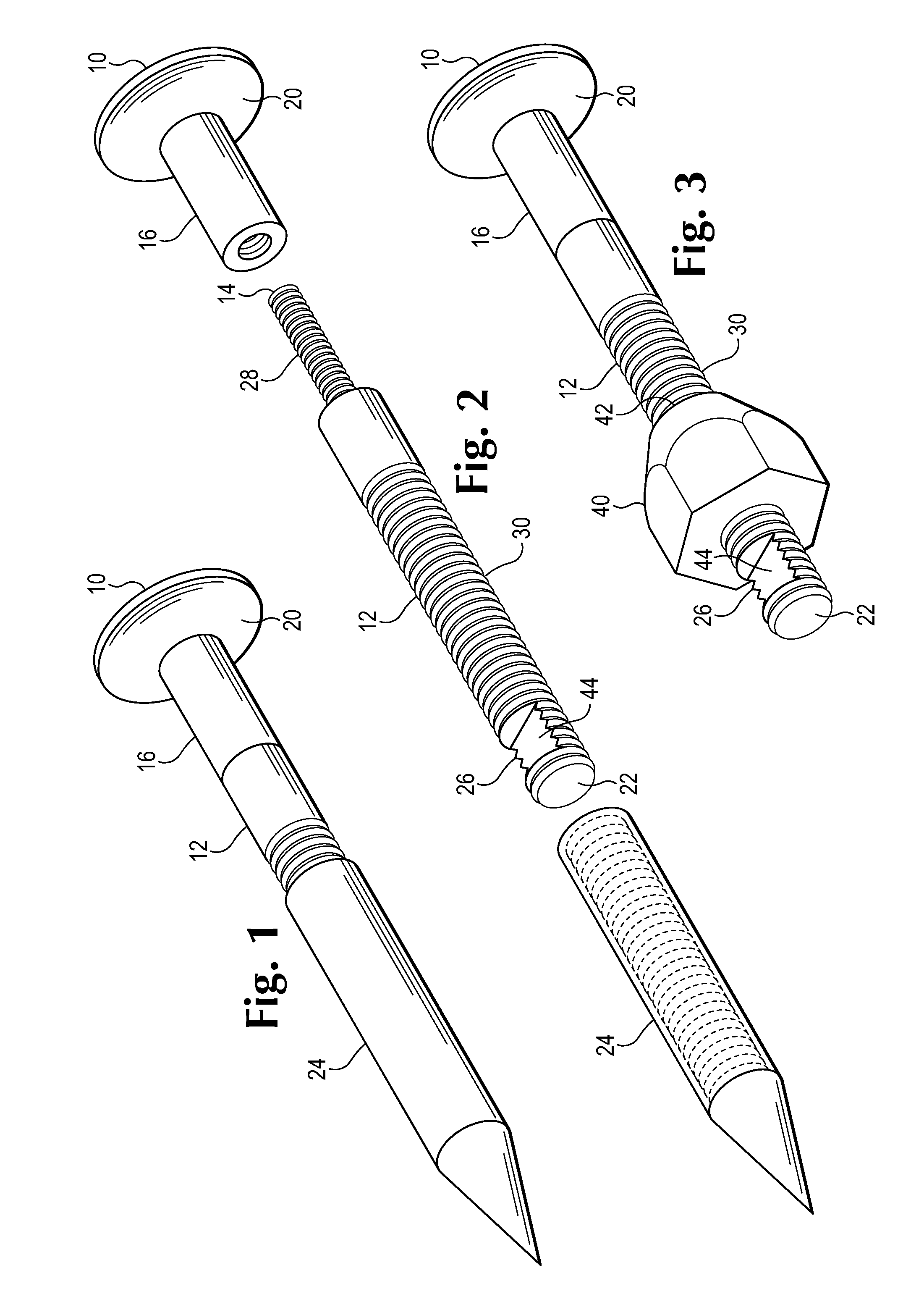
[0020]Referring now to the drawings which form a part of this disclosure, in one embodiment, a base component 10 made of steel, titanium or plastic, or other such material is attached to the distal end 14 of an elongate member 12. The base component 10 may be threaded onto the member or otherwise remova...


PUM


Abstract

Apparatus and method of use which can be used to immobilize maxilla and mandible in dental occlusion utilizing the tissue of the interdental space.

Description

CROSS-REFERENCE TO RELATED APPLICATIONS[0001]This application claims the benefit of U.S. Provisional Application Nos. 61 / 400,934, filed Aug. 4, 2010, 61 / 338,192, filed Feb. 16, 2010, and 61 / 279,894, filed Oct. 27, 2009.BACKGROUND OF THE INVENTION[0002]1. Field of Invention[0003]The present invention is designed to treat mandible and facial fractures by improving the technique of maxillo-mandibular fixation (MMF) or intermaxillary fixation (IMF).[0004]2. Prior Art[0005]Those skilled in the art of treating fractures of the mandible are familiar with the current techniques in repairing mandible and other facial fractures. Most mandible fracture repairs require immobilization of the jaws in dental occlusion during healing. Achieving stable maxilla-mandibular fixation requires immobilization of the powerful jaw muscles using points of fixation which are strong enough to resist considerable force.[0006]Stable immobilization of the jaws in dental occlusion is achieved by affixing the mandi...

Claims


Application Information

Patent Timeline
IPC IPC(8): A61B17/84
CPCA61B17/842A61B17/8685A61B17/8625
Inventor STUPAK, HOWARD D.
Owner STUPAK HOWARD D
Learn More