
Orthodontic accessory arch bar

a technology accessory brackets, which is applied in the field of orthodontic accessory brackets, can solve the problems of insufficient strength of orthodontic arch wires to quickly correct the bite and finish the case, the difficulty of lingual wire placement, etc., and achieve the effect of quick widening the molar arch width

Inactive Publication Date: 2005-06-16
GRAHAM NEIL JOHN
View PDF11 Cites 19 Cited by
  • Summary
  • Abstract
  • Description
  • Claims
  • Application Information

AI Technical Summary

Benefits of technology

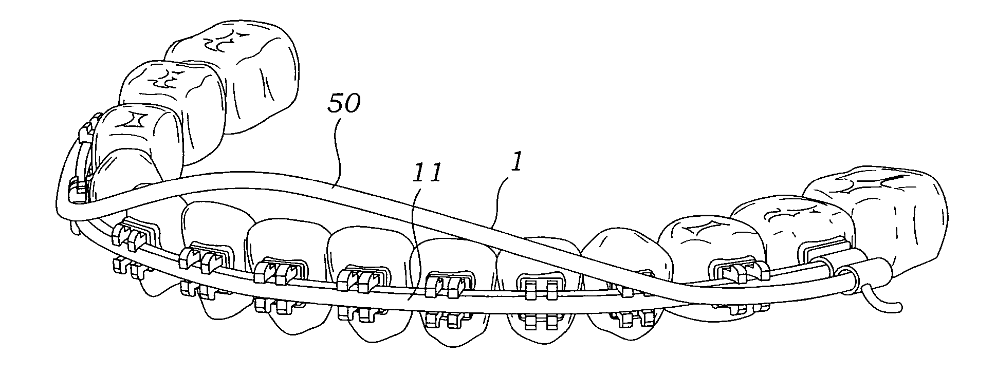
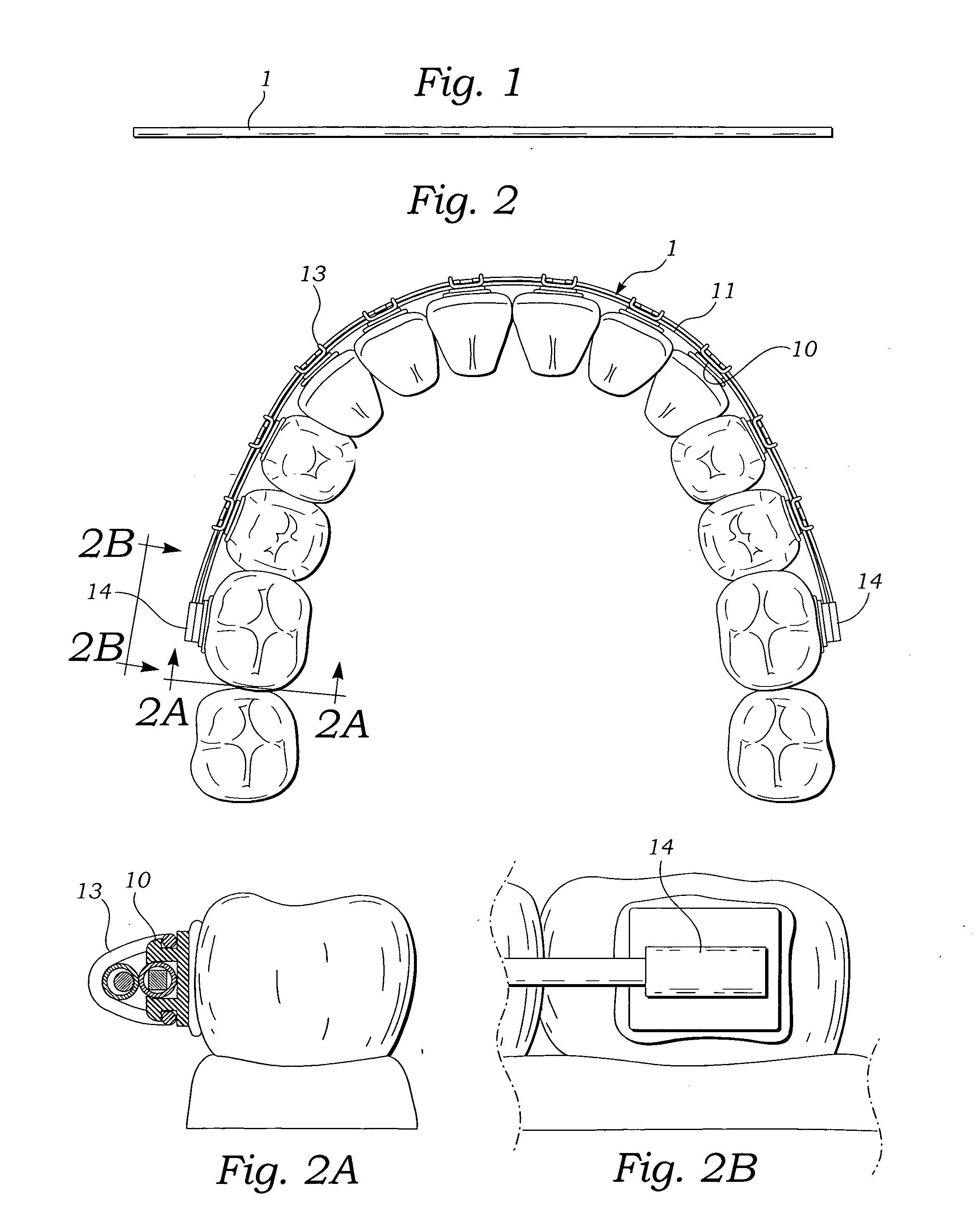
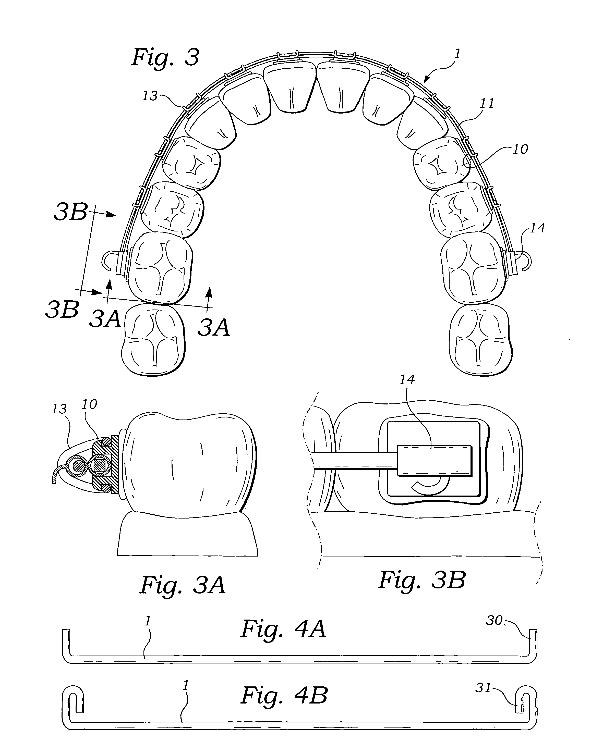
[0004] The present invention is directed to a labial accessory arch bar attached to a conventional orthodontic appliance. The arch bar piggybacks the orthodontic arch wire and extends, just as the arch does, on the labial of the teeth, from the molar area on one side of the mouth to molar area on the opposite side of the patient's mouth. The arch wire may be attached to the orthodontic appliance using the same ligature ties used to tie the arch wire to the orthodontic brackets. Elastomeric eyelets are an ideal method of ligation. The arch bar ends may be inserted into a headgear tube on the appliance or configured to engage the arch wire. In a preferred embodiment the arch bar is configured straight prior to placement on the orthodontic appliance which quickly widens the molar arch width which is particularly useful in widening of the upper arch width in the correction of a posterior dental cross bite.

Problems solved by technology

The formation, placement, and adjustment these lingual wires are more difficult than the labial wires because of the lingual location.
When adjusted correctly the lingual wires have greater control over the molar width than the labial arch wires, but are in a more difficult area of the mouth to work in.
Occlusion of the teeth in a normal, or Class 1, bite helps coordinate the bite; but correction of the bite to a Class 1 bite often doesn't occur until the end of orthodontic treatment which doesn't allow enough time for the occlusion to coordinate the bite.
If coordination of the bite has not been accomplished by the end of treatment the orthodontic arch wires are not strong enough to quickly correct the bite and finish the case.
Lingual arch wires can be more effective at this point and can have accessory wires added to them to widen the arch form; however, lingual arch accessory wires do not have precise control over the dental arch form.

Method used


Image

  • Orthodontic accessory arch bar
  • Orthodontic accessory arch bar
  • Orthodontic accessory arch bar

Examples


Embodiment Construction

[0032] Referring to FIGS. 1-13 the accessory arch bar 1 is a wire of sufficient length to be attached, or piggy-backed to an installed orthodontic arch wire 11. The arch bar diameter can be 0.020-0.60 inch. The cross section of the arch bar is usually circular but can be other shapes, such as square or rectangular. The composition of the arch bar can be stainless steel. In a preferred embodiment the arch bar 1 is 0.027 inch in diameter and comprised of Ti beta 3 wire. In this embodiment the arch bar 1 is gentle for the patient, but because of its memory moves the teeth quickly.

[0033] As shown in FIG. 2, an orthodontic appliance is comprised of brackets 10 placed on the outer surface of the patient's teeth 12. An arch wire 11 is connected to the brackets 10 and held in place with ties 13 which can be metal wire or elastomeric eyelets. In FIG. 3 the accessory arch bar 1 is shown attached to the orthodontic appliance using the same ties 13 which ligate the arch wire 11 to the orthodon...


PUM


Abstract

An orthodontic accessory arch bar for orthodontic therapy which is adapted for attachment to the buccal surface of a fixed orthodontic appliance. The accessory arch bar is comprised of wires heavier than orthodontic arch wires which gives the accessory arch bar greater control over the width and form of the dental arch. The orthodontic accessory wire may be configured to widen or narrow the dental arch, coordinate the bite, precisely shape the dental arch, open or close the anterior bite, and correct a cant of the anterior occlusal plane.

Description

FIELD OF THE INVENTION [0001] The present device relates to an accessory arch bar which is used to form the dental arch of an orthodontic patient when it is attached outwardly adjacent to the arch wire of an orthodontic appliance. BACKGROUND OF THE INVENTION [0002] The orthodontic procedures, today, for straightening teeth involve the placement of orthodontic brackets with attached orthodontic arch wires on the external or labial surfaces of the teeth. The labial surfaces of the teeth are the most common locations for fixed orthodontic appliances because of ease of access for the dentist and comfort for the patient. Orthodontic treatment is comprised of a succession of orthodontic arch wires from small diameter round wires, to larger round wires, to larger wires rectangular in cross-section. Orthodontic arch wires have been chosen in size, shape, and composition primarily for individually and mutually aligning the teeth and exert very little formation pressure over the width and sha...

Claims


Application Information

Patent Timeline
IPC IPC(8): A61C3/00A61C7/12A61C7/20
CPCA61C7/20A61C7/12
Inventor GRAHAM, NEIL JOHN
Owner GRAHAM NEIL JOHN
Learn More