Methods and circuitry for reconfigurable seu/set tolerance

a technology of seu/set tolerance and circuitry, applied in the field of circuitry, can solve the problems of low reliability, low capacity, and high cost of circuitry testing, and achieve the effect of speeding up the speed and ease of design of redundancy and reducing the number of errors

Inactive Publication Date: 2011-01-20
NASA
View PDF12 Cites 17 Cited by
  • Summary
  • Abstract
  • Description
  • Claims
  • Application Information

AI Technical Summary

Benefits of technology

[0028]Another possible advantage of the present invention is that built-in hardware redundancy attendant speed and ease of design can be utilized without giving up high capacity for other parts of an application.
[0029]However, it will be understood that the above-listed objectives and / or advantages of the invention are intended only as an aid in quickly understanding aspects of the invention, are not intended to limit the invention in any way, and therefore do not form a comprehensive or restrictive list of objectives, and / or features, and / or advantages.
[0030]Accordingly, one embodiment of the invention provides a reconfigurable programmable integrated circuit which may comprise a plurality of programmable functional elements, programmable interconnections for the programmable functional elements, and a mode control operably connected with the programmable functional elements. In a redundant mode of operation, the programmable functional elements produce an output which is voted. In a split channel mode of operation, the programmable functional elements produce an output which is not voted.
[0031]The programmable functional elements may be organized into a plurality of blocks, which may each be physically positioned on an integrated circuit. In this embodiment, each block is preferably sufficiently physically separated from others of the plurality of blocks to prevent a single SEU / SET causing an error in two blocks at the same time.
[0032]The reconfigurable programmable integrated circuit may also comprise a plurality of voters electrically connected to the programmable functional elements. In one embodiment, the plurality of voters is connected to provide a triple redundant mode of operation.
[0033]The reconfigurable programmable integrated circuit may further comprise pre-wired electrical continuous connections without switches between the plurality of voters in the plurality of different blocks.

Problems solved by technology

End-user designed techniques can be used to provide tailor made solutions which are more efficient with higher data capacity but may be less reliable due to greater difficulty in providing reliable SEU / SET mitigation.
However, there are many papers on the pitfalls of taking an FPGA and programming SEU / SET by adding redundancy through the firmware programming.
For example, there may be some underlying common source of error that is unknown due to the underlying structure of the chip.
Moreover, the circuitry is expensive to test due to the requirement for testing within an environment with sufficient radiation to cause errors.
However, software programming techniques may be less efficient, may take more time, and may intrude upon the application design.
Without TMR, scrubbing reduces the time period (potentially indefinite) during which the device is functioning erroneously.
Occasionally data is directly obtained by placing test specimens in Low Earth Orbit, but rarely in other instances due to impracticality.
Combating these faults requires more complex algorithmic or heuristic approaches that check whether outputs meet user-defined reasonableness criteria.
The above approaches do not solve the aforementioned problems.
The complexity and difficulty of end-user-designed mitigation is encountered over and over through the life cycle of the application.

Method used


Image

  • Methods and circuitry for reconfigurable seu/set tolerance
  • Methods and circuitry for reconfigurable seu/set tolerance
  • Methods and circuitry for reconfigurable seu/set tolerance

Examples


Embodiment Construction

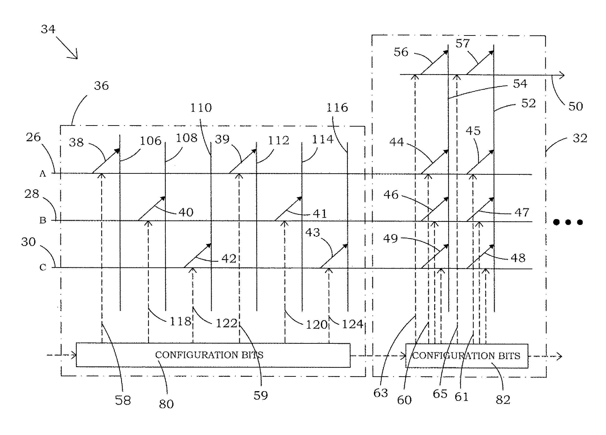
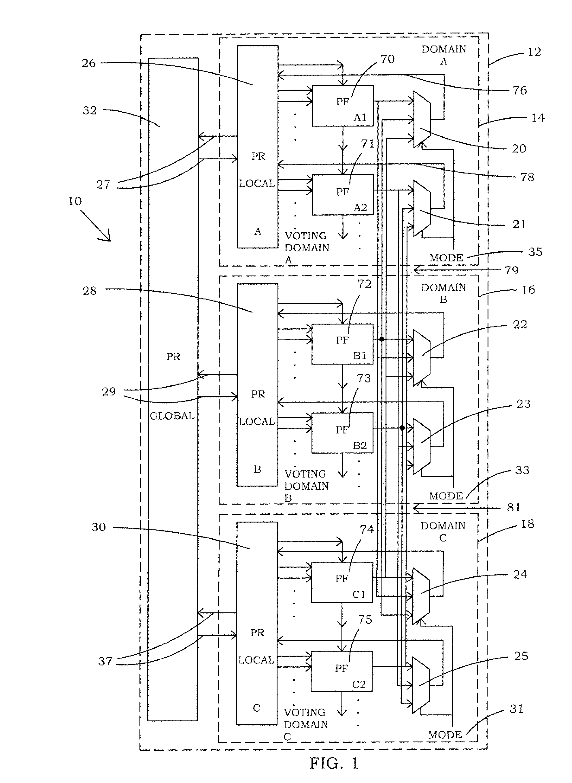
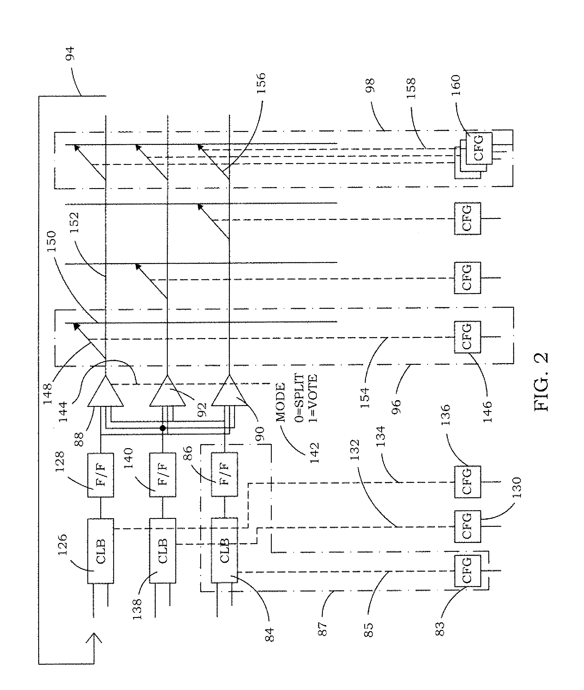
[0058]One embodiment of the present invention enables reconfiguration of SEU / SET tolerance in selective physical locations within programmable logic devices (PLDs). For example, circuitry internal to an integrated circuit may be selectively reconfigured for either redundant or non-redundant operation. In this way, the application can be tailor made for the right mix of reliability and high capacity. The present invention can be utilized to provide more quickly designed, reliable firmware redundancy where needed, while permitting other areas of integrated circuits to operate in a single channel mode of operation having high data capacity.

[0059]Even incorporating the dual mode of operation capability, the device may retain up to 95% of the capacity, or possibly more, as compared with a device that does not utilize pre-wired redundant operation. In accord with the present invention, developers can design hardware redundancy into applications without encountering the many pitfalls of at...


PUM

PropertyMeasurementUnit
spread distanceaaaaaaaaaa
timeaaaaaaaaaa
volatileaaaaaaaaaa

Abstract

A device is disclosed in one embodiment that has multiple identical sets of programmable functional elements, programmable routing resources, and majority voters that correct errors. The voters accept a mode input for a redundancy mode and a split mode. In the redundancy mode, the programmable functional elements are identical and are programmed identically so the voters produce an output corresponding to the majority of inputs that agree. In a split mode, each voter selects a particular programmable functional element output as the output of the voter. Therefore, in the split mode, the programmable functional elements can perform different functions, operate independently, and / or be connected together to process different parts of the same problem.

Description

ORIGIN OF THE INVENTION[0001]The invention described herein was made by employee(s) of the United States Government and may be manufactured and used by or for the Government of the United States of America for governmental purposes without the payment of any royalties thereon or therefore.BACKGROUND OF THE INVENTION[0002]1. Field of the Invention[0003]The present invention relates generally to circuitry which may be operated in environments whereby the circuitry is subject to single event upsets (SEU) and / or single event transients (SET) and, more specifically, to circuitry which is reconfigurable for adjusting the SEU / SET tolerance thereof.[0004]2. Description of Related Art[0005]The Field Programmable Gate Array (FPGA) is a type of programmable logic device (PLD). The FPGA may comprise an array of programmable tiles or programmable functional elements such as, for example, input / output blocks (IOBs), configurable logic blocks (CLBs), took up tables (LUTs), dedicated random access ...

Claims


Application Information

Patent Timeline
Patent Type & Authority Applications(United States)
IPC IPC(8): H03K19/003H01S4/00
CPCH03K19/0033H03K19/0075H03K19/17736Y10T29/49002H03K19/17764H03K19/23H03K19/17748
Inventor SHULER, JR., ROBERT L.
Owner NASA
Why Eureka
Try Eureka