High efficiency positive displacement thermodynamic system

Active Publication Date: 2011-05-05
STAFFEND GILBERT
View PDF6 Cites 71 Cited by
  • Summary
  • Abstract
  • Description
  • Claims
  • Application Information

AI Technical Summary

Benefits of technology

[0013]The system of the present invention enables a more efficient thermodynamic cycle than heat pumps of the prior art because it utilizes an air aspirated open loop configuration in combination with an integral combustion chamber that burns a fuel in the working fluid and combined with an energy receiving device that reclaims available pressure energy from the working fluid. As a result, the system is more readily adapted to heat a target space in extremely cold conditions and to conserve energy by harnessing at least some of the residual energy in the working fluid that exists in the form of a pressure differential above the ambient atmospheric conditions.
[0014]According to another aspect of this invention, a positive displacement rotating vane-type device includes a rotor rotatably supported within a stator housing. The stator housing has opposite longitudinal ends. A plurality of vanes are operatively disposed between the rotor and the stator housing and divide the interstitial space between the rotor and stator housing into a plurality of compression and expansion chambers, each chamber being defined by the space between adjacent vanes. As the rotor rotates relative to the stator housing, the chambers defined between adjacent vanes sequentially and progressively transition between compression and expansion stages in a continuum so that the working fluid is simultaneously compressed in compression chambers and expanded in expan

Problems solved by technology

While such known heat pump systems are adequate in many climates, they are frequently unable to provide adequate heating during extremely cold conditions.
This is because a typically sized system is not capable of cooling the working fluid (even in the ca

Method used


Image

  • High efficiency positive displacement thermodynamic system
  • High efficiency positive displacement thermodynamic system
  • High efficiency positive displacement thermodynamic system

Examples


Embodiment Construction

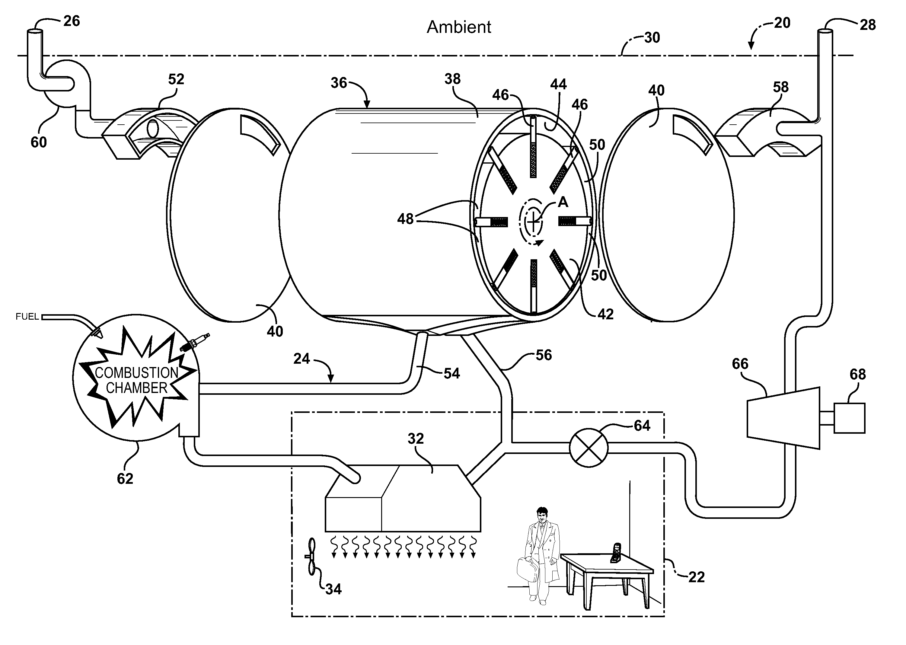
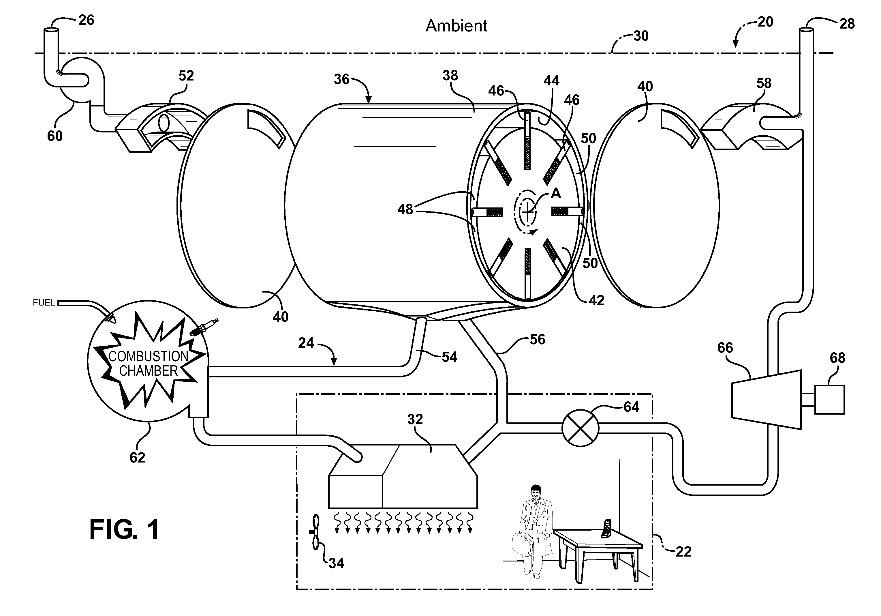
[0021]Referring to the Figures, wherein like numerals indicate corresponding parts throughout the several views, one embodiment of the invention is shown in FIG. 1 as an open loop air aspirated hybrid heat pump and heat engine system 20 for selectively heating and cooling a target space 22. The target space 22 can be an interior room in a building, the passenger compartment of an automobile, a computer enclosure, or any other localized space to be heated and / or cooled. The working fluid of the system 20 in this embodiment is most preferably air, however in general the principles of this invention will permit other substances to be used for the working fluid including multi-phase refrigerants in suitable closed-loop configurations.

[0022]The hybrid heat pump and heat engine system 20 includes a working fluid (e.g., air) flow path 24, generally indicated in FIG. 1, extending from an inlet 26 to an outlet 28. The inlet 26 receives working fluid (air in this example) from an ambient sour...


PUM


Abstract

An air aspirated hybrid heat pump and heat engine system (20) for selectively heating and cooling a space (22) having an flow path (24) including a compressor (76), a heat exchanger (32), an expander (78), and a generator (68). A combustion chamber (62) is in the flow path (24) for combusting a fuel in the air during a high heating mode. The heat exchanger (32) dissipates the heat from the air, and the expander (78) depressurizes the air while powering the generator (68). Also included is a positive displacement rotating vane-type device (36) having a stator housing (38) extending between longitudinal ends (40). A compression chamber inlet (52) and an expansion chamber outlet (58) are located on opposite longitudinal ends (40) of the stator housing (38) to be in simultaneous communication with the same chamber (48, 50)). A fluid enters the device through the compression chamber inlet (52) and pushes fluid out of the expansion chamber outlet (58).

Description

CROSS REFERENCE TO RELATED APPLICATION[0001]This application claims the benefit of U.S. Provisional Application Ser. No. 61 / 256,559 filed Oct. 30, 2009.BACKGROUND OF THE INVENTION[0002]1. Field of the Invention[0003]A thermodynamic heat pump and heat engine system for selectively heating and cooling a target space, and more particularly such a thermodynamic system in which ambient air comprises the working fluid therefor.[0004]2. Description of the Prior Art[0005]Thermodynamic systems in the form of heat pumps are used in the prior art to alternatively heat or cool a target space in standard heating / cooling modes. Heat pumps generally include a compressor, two heat exchangers, and an expander all disposed in a common fluid flow path. Most heat pump systems are of the closed loop type in which the working fluid, typically a two-phase refrigerant, is circulated through the system so as to absorb heat through one of the heat exchangers and to reject heat from the other heat exchanger. ...

Claims


Application Information

Patent Timeline
IPC IPC(8): F01K25/00F25B27/00F25B7/00F04C2/00
CPCF01C13/04F01K23/06F04C18/3441F01K25/00F04C29/04F25B9/004F25B30/00F04C23/005
Inventor STAFFEND, GILBERT
Owner STAFFEND GILBERT
Why Eureka
Try Eureka