Cable connector

Inactive Publication Date: 2011-05-05
JAGUAR LAND ROVER LTD
View PDF5 Cites 8 Cited by
  • Summary
  • Abstract
  • Description
  • Claims
  • Application Information

AI Technical Summary

Benefits of technology

The present invention provides a cable connector that allows two bowden cables (one connected to an actuator and another to a slave) to be joined together. This connector holds the two cables' sleeves securely while allowing them to move independently through a special mechanism. This results in limited linear motion between the two cables only in one direction, preventing any unwanted movements from affecting the overall performance of the system.

Problems solved by technology

The technical problem addressed in this patent is how to improve the design of a cable connector that allows for better utilization of space and more efficient operation of an emergency park release system in motor vehicles with automatic transmission systems.

Method used


Image

  • Cable connector
  • Cable connector
  • Cable connector

Examples


Embodiment Construction

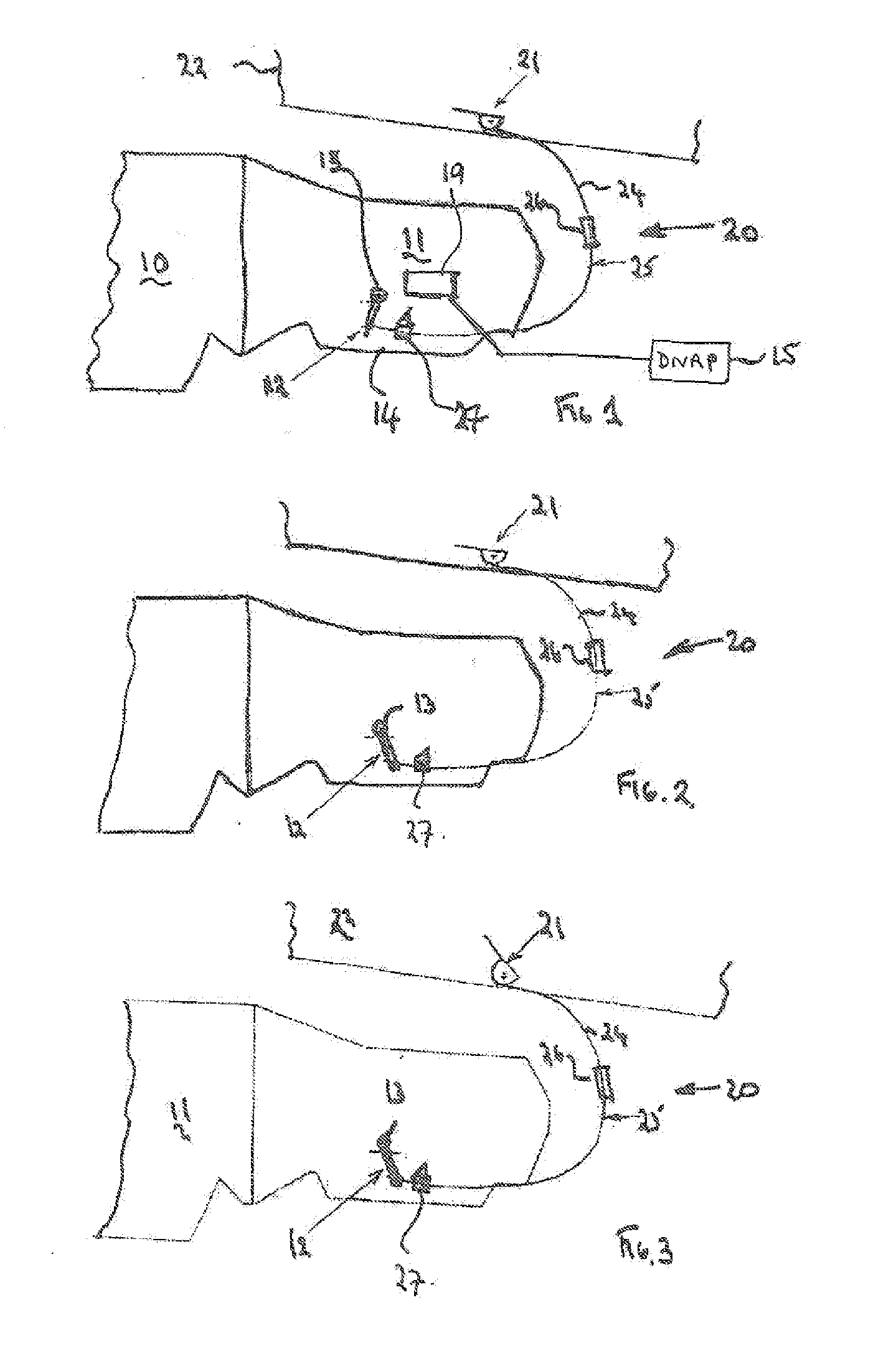
[0019]With reference to FIG. 1 there is shown a vehicle ‘e-shift’ automatic transmission 11 mounted on the rear of a vehicle engine 10. The transmission 11 has a release lever 12 mounted externally of the transmission housing 14 and attached to a shaft 13 which rotates when the parking brake is engaged and disengaged on a driver controlled selector. The movement of the shaft 13 causes the lever 12 to rotate backwards and forwards. In the present embodiment the lever 12 is shown in FIG. 1 as rotated forward with the parking brake engaged in the park mode with power off and in FIG. 2 rotated backward with the parking brake disengaged and the transmission in drive. The ‘e-shift’ transmission includes a driver operable electrical transmission control 15 connected to an electro-hydraulic device 19 housed inside the transmission housing 14. The control 15 selects the mode of operation of the transmission using electrical signals to prompt a mode change via electro-hydraulic device 19. Whe...


PUM


Abstract

A control cable system for interconnecting an actuator (21) with a slave device (12) and comprising two Bowden cables (24,25) each comprising a sleeve (31,33) and inner traction cord (32,34) and a cable connector (26) for interconnecting the two cables, one cable (24) connecting to the actuator (21) and the second cable (25) connecting to the slave device (12). the connector (26) holding the two sleeves (31,33) in a fixed relationship with the two traction cords (32,34) being interconnected via a connecting device (29) which permits movement of the slave device (12) and second traction cord (33) without transmission of said movement to the said one traction cord and which transmits movement from the actuator (21) to said second traction cord (33).

Description


Claims


Application Information

Patent Timeline
Owner JAGUAR LAND ROVER LTD
Why Eureka
Try Eureka