Electromagnetic pump

a technology of electromagnetic pumps and eddy currents, which is applied in the direction of check valves, liquid fuel engines, functional valve types, etc., can solve the problems of the prior art manufacturing process of electromagnetic pumps b>100/b>, and achieve the effect of reducing the occurrence of eddy currents

Active Publication Date: 2016-05-17
GOTEC SA
View PDF4 Cites 2 Cited by
  • Summary
  • Abstract
  • Description
  • Claims
  • Application Information

AI Technical Summary

Benefits of technology

[0016]Advantageously, the valve provided in the electromagnetic pump of the present invention has a simple construction compared to the valves used in the prior art. In the electromagnetic pump of the present invention a single valve only is required to control the flow of fluid through the aperture in the piston, and to prevent fluid from back-flowing from on outlet conduit back into the electromagnetic pump and into the interface between the piston and cylinder. The single valve comprises a single cap and therefore advantageously has much less components compared to the valves used in the pumps of the prior art. The simplified construction and reduction in the number of parts leads to an electromagnetic pump which is easier and less costly to manufacture.
[0019]Walls which define the annular recess may restrict the linear movement of the cap; when the cap is moved towards its second position, the one or more projections which are arranged to project into the annular recess will eventually abut the side walls defining the recess, thus preventing further linear movement of the cap. Thus, by selecting the appropriate width for the annular recess, and the appropriate width for the one or more projections, one can control the extent to which the cap can move and thus control the size of the passage which is provided for fluid to flow out of the cavity in the piston, when the cap is in its second position.
[0025]The single cap may comprise a bowl-shape profile. The bowl-shape profile will ensure that when the piston is in its second position and the single cap is in its second position, the cap will offer less resistance to fluid flowing out of the cavity in the piston. Also the bowl-shape profile of the single cap will ensure that when the piston is in its first position and the single cap has been moved to its first position, then any back-flowing fluid which is flowing in the direction from the outlet conduit back toward the piston, will push against the single cap to cause the single cap to achieve a tighter closure of the aperture in the piston. As the bowl-shape profile of the single cap can take advantage of the pressure of the flowing fluid within the electromagnetic pump to achieve improved closure of the valve, less precise shaping and design of the single cap is required to achieve sufficient closure of the valve.
[0027]The seal may comprise an O-ring. It will be understood that the seal may comprise any other type of annular rubber ring. The seal may be positioned between the single cap and an outlet conduit of the electromagnetic pump. The collaboration between the cap and the O-ring seal thus blocks the flow of fluid through the piston and around the piston when the piston is biased in its second position; a single valve is sufficient to fill both functions.
[0032]The electromagnetic pump may further comprise ferromagnetic parts, for example a cylinder may comprise one or more ferromagnetic parts. Preferably, the cylinder comprises a first and second ferromagnetic part and an insulating part interposed between the first and second ferromagnetic parts. The insulating part may comprise plastic. The cylinder may comprise a laminate structure so as to reduce the occurrence of eddy currents.
[0033]The electromagnetic pump may further comprise a ferromagnetic frame member arranged to provide structural support and wherein the ferromagnetic frame member is a configured to be a laminate structure so as to reduce the occurrence of eddy currents.

Problems solved by technology

The requirement for precise design and shaping of the plug members 151,153 make the manufacturing process of the prior art electromagnetic pumps 100 expensive.

Method used


Image

  • Electromagnetic pump
  • Electromagnetic pump
  • Electromagnetic pump

Examples


Embodiment Construction

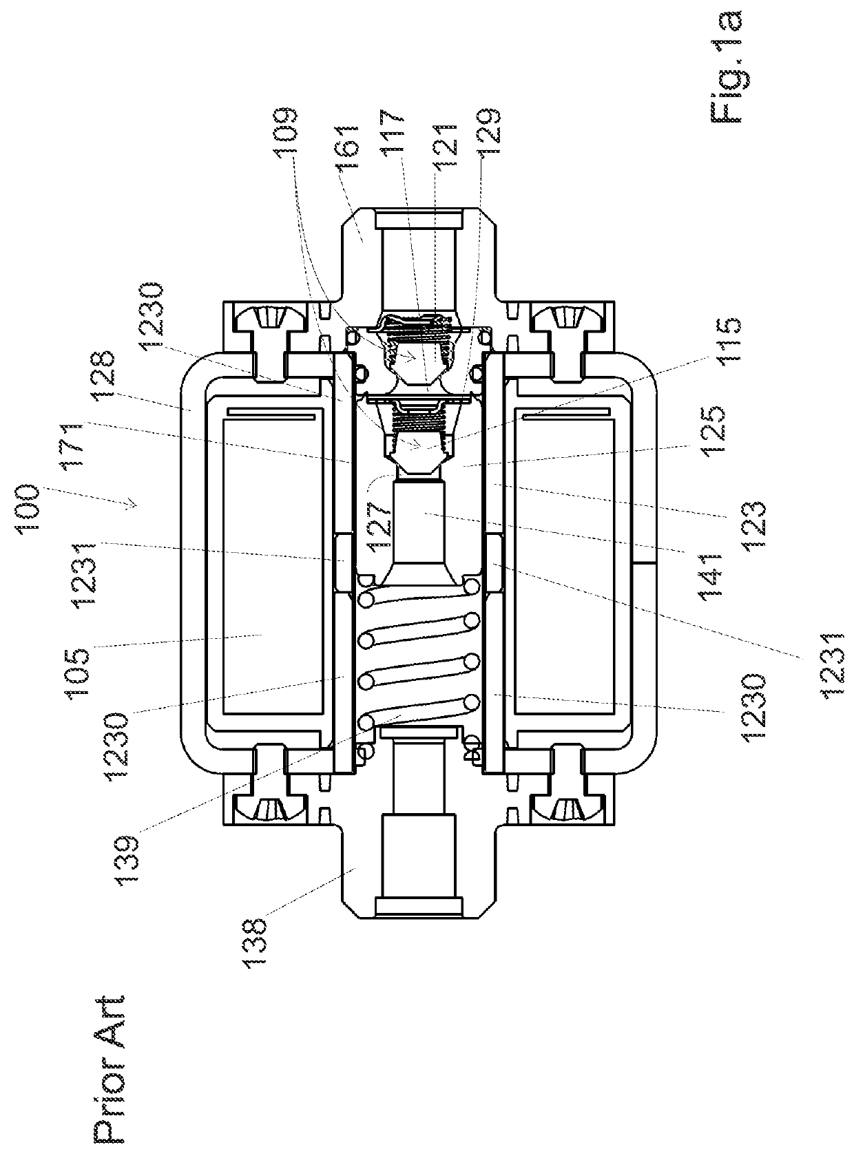
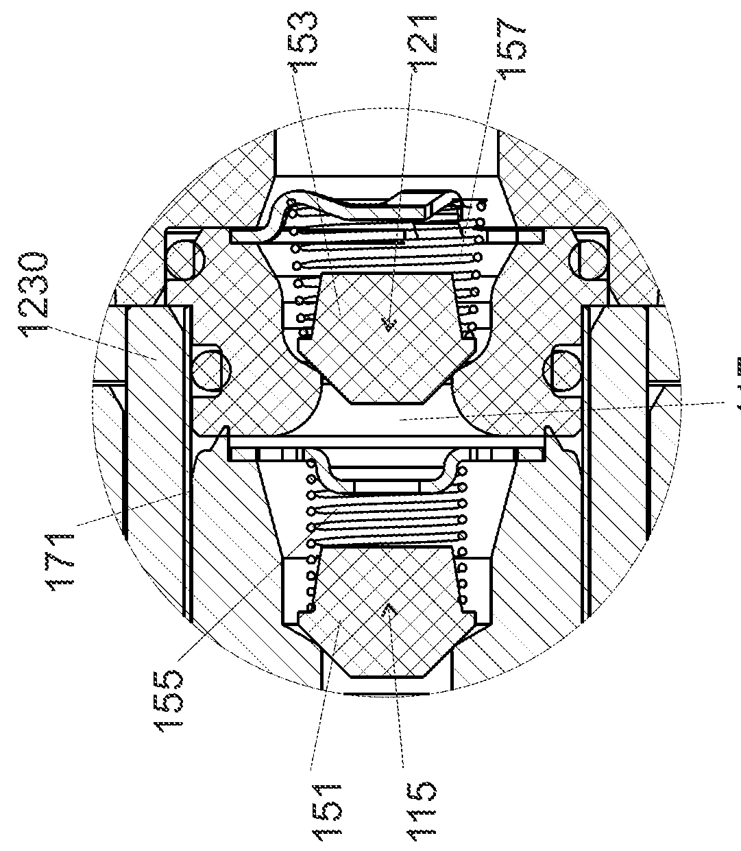
[0052]FIGS. 2a and 2c each provide a cross sectional view of an electromagnetic pump 20 according to one embodiment of the present invention. FIG. 2b provides a magnified view of the valve used in the electromagnetic pump 20 shown in FIG. 2a and FIG. 2d provides a magnified view of the valve in the electromagnetic pump 20 shown in FIG. 2c.

[0053]The electromagnetic pump 20 comprises a cylinder 23 and a piston 25 assembly. The cylinder 23 comprises four parts; a first and second ferromagnetic part 35a,b, a non magnetic portion 36 which is interposed between the first and second ferromagnetic parts 35a,b, and a tube 19 within the components 35a, 35b and 36.

[0054]The piston 25 comprises a chamber 41 defined therein which is suitable for receiving fluid. The chamber 41 is arranged in fluid communication with an inlet conduit 38. The piston 25 further comprises an aperture 27 defined in a first end 29 thereof. The piston 25 is arranged to extend within the cylinder 23 and is configured s...


PUM


Abstract

An electromagnetic pump includes a coil configured to conduct an alternating current, a cylinder, and a piston assembly. The piston includes a cavity configured to receive fluid and an aperture defined in a first end thereof The piston is arranged within the cylinder to define an interface between the piston and the cylinder, and the piston is configured to move linearly between a first position and a second position within the cylinder. The piston is positioned in the electromagnetic pump such that it is within a magnetic field which is generated by the coil when the coil conducts a current.

Description

[0001]The present application claims priority of U.S. application 61 / 622617, filed on Apr. 11, 2012, the contents of which is hereby enclosed by reference.FIELD OF THE INVENTION[0002]The present invention concerns an electromagnetic pump and in particular an electromagnetic pump which comprises a simplified valve.DESCRIPTION OF RELATED ART[0003]FIG. 1a provided a cross sectional view of an electromagnetic pump 100 according to the prior art and FIG. 1b provides a frontal view of the electromagnetic pump 100 shown in FIG. 1a. [0004]The electromagnetic pump 100 comprises a cylinder 123 and piston 125 assembly.[0005]The cylinder 123 comprises four parts; a first and a second ferromagnetic part 1230, a non magnetic portion 1231 which is interposed between the first and second ferromagnetic parts 1230, and a tube 171 within the components 1230 and 1231. The piston 125 is arranged within the tube 171 to define an interface between the piston 125 and cylinder 123. The piston 125 is arrange...

Claims


Application Information

Patent Timeline
Patent Type & Authority Patents(United States)
IPC IPC(8): F04B53/12F16K15/02F04B17/04
CPCF04B53/125F04B17/044F04B17/046F04B53/12F04B53/123F16K15/021
Inventor MAYORAZ, PIERRE
Owner GOTEC SA
Why Eureka
Try Eureka