Apparatuses and methods for controlling movement of components

a technology of components and actuators, applied in the direction of couplings, nuclear elements, greenhouse gas reduction, etc., can solve the problems of wear and fatigue on the parts of the jet pump, and achieve the effect of reducing wear and fatigu

Active Publication Date: 2017-03-07
GE HITACHI NUCLEAR ENERGY AMERICAS
View PDF26 Cites 0 Cited by
  • Summary
  • Abstract
  • Description
  • Claims
  • Application Information

AI Technical Summary

Benefits of technology

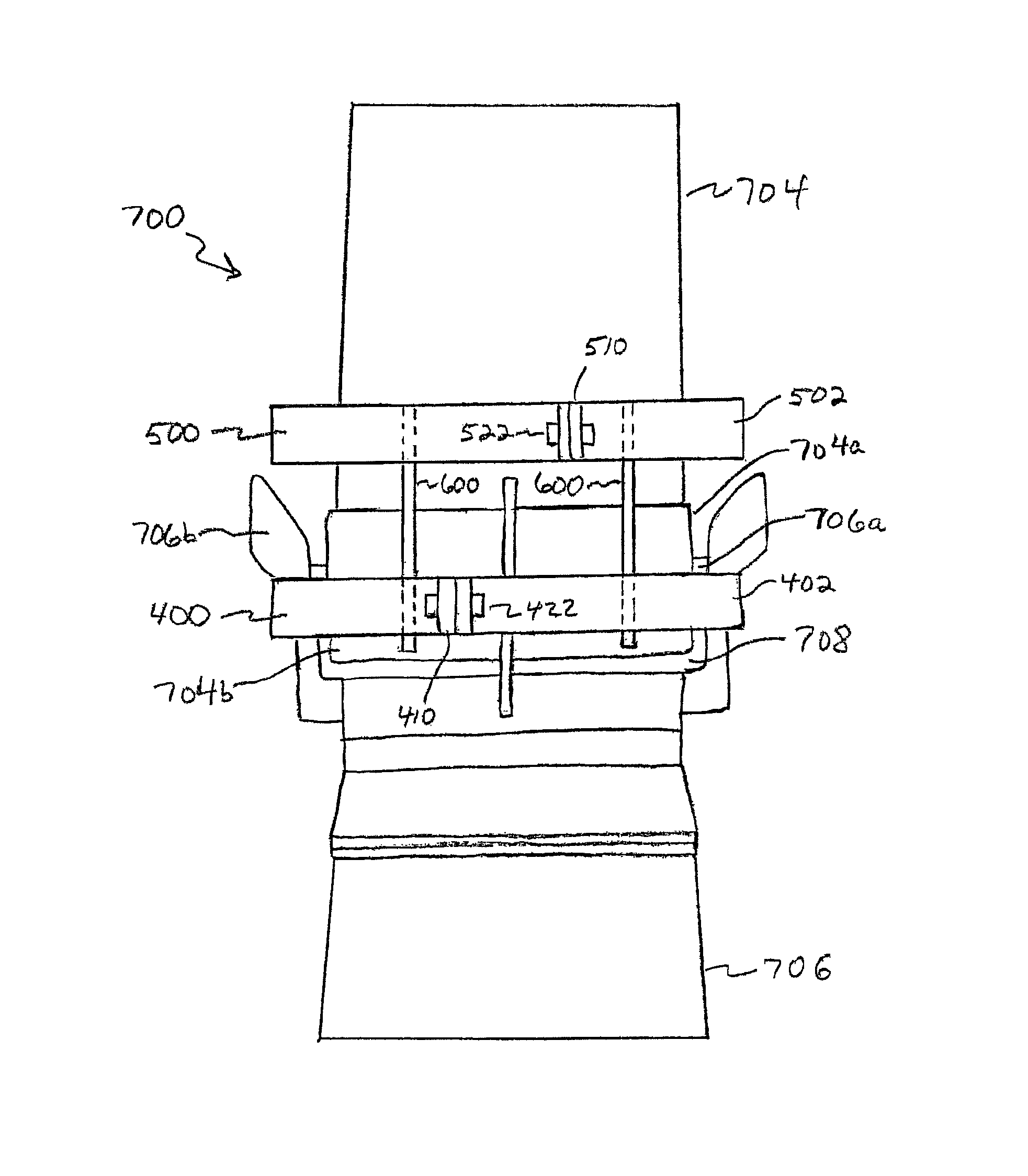
[0016]In example embodiments, the connectors may limit linear movement of the first clamp relative to the second clamp in the second direction.
[0033]In example embodiments, the first clamp, second clamp, and connectors may limit rotational movement of the inlet mixer relative to the diffuser about the axial direction of the jet pump assembly.

Problems solved by technology

The resultant increased vibration levels and corresponding vibration loads on the piping and supports may cause jet pump component degradation from wear and fatigue.
High levels of FIV may be possible in certain jet pump designs at some abnormal operational conditions having increased leakage rates.

Method used


Image

  • Apparatuses and methods for controlling movement of components
  • Apparatuses and methods for controlling movement of components
  • Apparatuses and methods for controlling movement of components

Examples


Embodiment Construction

[0046]Example embodiments will now be described more fully with reference to the accompanying drawings. Embodiments, however, may be embodied in many different forms and should not be construed as being limited to the embodiments set forth herein. Rather, these example embodiments are provided so that this disclosure will be thorough and complete, and will fully convey the scope to those skilled in the art. In the drawings, the thicknesses of layers and regions are exaggerated for clarity.

[0047]It will be understood that when an element is referred to as being “on,”“connected to,”“electrically connected to,” or “coupled to” to another component, it may be directly on, connected to, electrically connected to, or coupled to the other component or intervening components may be present. In contrast, when a component is referred to as being “directly on,”“directly connected to,”“directly electrically connected to,” or “directly coupled to” another component, there are no intervening comp...


PUM


Abstract

An apparatus for controlling movement of a first component integrated with a second component may include a first clamp configured to engage the first component, a second clamp configured to engage the second component, and a plurality of connectors configured to connect the first and second clamps. The connectors may allow movement of the first clamp relative to the second clamp in a first direction between the first and second clamps. The connectors may limit movement of the first clamp relative to the second clamp in a second direction perpendicular to the first direction.

Description

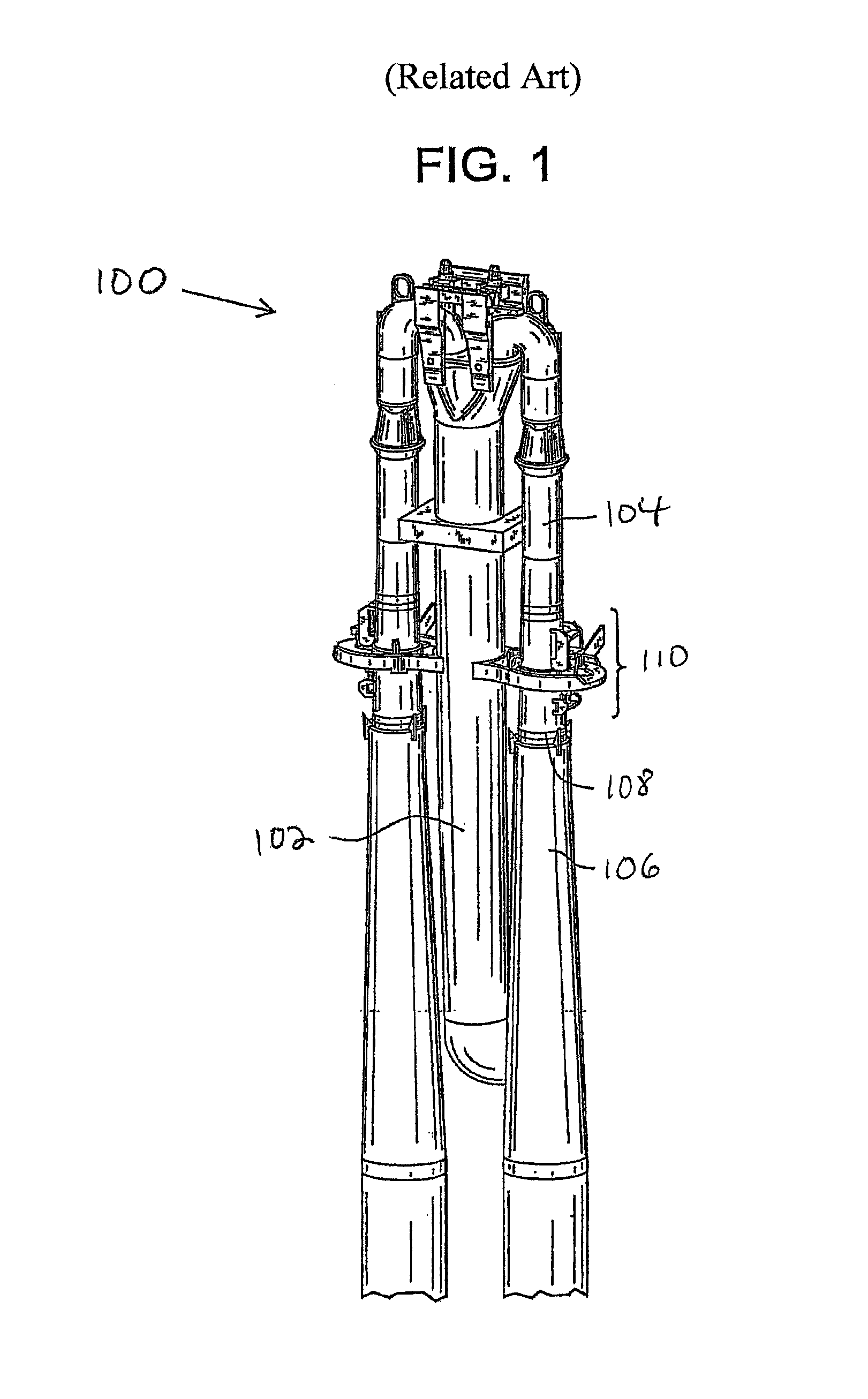
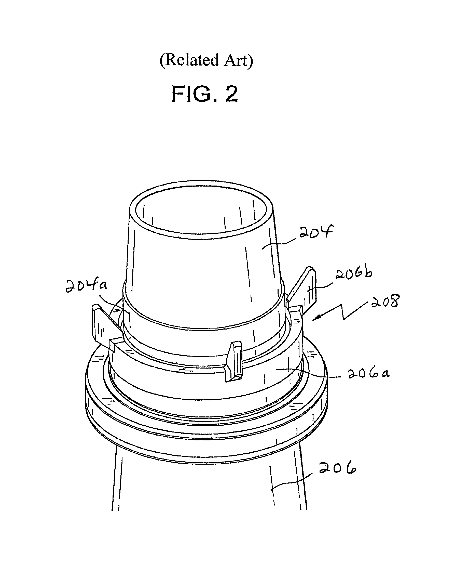
BACKGROUND[0001]1. Field[0002]Example embodiments generally relate to apparatuses and methods for controlling movement of components. The controlling may involve, for example, allowing, limiting, and / or preventing movement. The components may be integrated components. Example embodiments also relate to nuclear reactor plants and to apparatuses and methods for controlling movement of components in the nuclear power plants.[0003]2. Description of Related Art[0004]A reactor pressure vessel (“RPV”) of a boiling water reactor (“BWR”) may have a generally cylindrical shape and may be closed at both ends (e.g., by a bottom head and a removable top head). A top guide may be spaced above a core plate within the RPV. A core shroud, or shroud, may surround the core and may be supported by a shroud support structure. The shroud may have a generally cylindrical shape and may surround both the core plate and the top guide. There may be a space or annulus located between the cylindrical RPV and th...

Claims


Application Information

Patent Timeline
Patent Type & Authority Patents(United States)
IPC IPC(8): G21C13/032G21C17/10G21C15/25
CPCG21C13/032G21C15/25G21C17/10Y02E30/40Y10T403/581Y02E30/30F16B2200/69
Inventor BASS, JOHN R.SPRAGUE, ROBIN D.
Owner GE HITACHI NUCLEAR ENERGY AMERICAS
Why Eureka
Try Eureka