

Droplet discharge device
a technology of droplet and discharge device, which is applied in the direction of weighing auxiliary device, weighing apparatus details, instruments, etc., can solve the problems of fluctuation of measurement object and inability to precisely measure weigh
- Summary
- Abstract
- Description
- Claims
- Application Information
AI Technical Summary
Benefits of technology
Problems solved by technology
Method used
Image

Examples
first embodiment
[0025]In the present embodiment, a characteristic example of a droplet discharge device, and a case of measuring a functional liquid discharged using this droplet discharge device, are described with reference to FIGS. 1 through 10.
[0026]First, a droplet discharge device 1 for discharging droplets to coat a workpiece will be described according to FIGS. 1 through 6. Various devices can be used for the droplet discharge device, but a conventional inkjet device is preferred. The inkjet device is configured and arranged to discharge miniscule droplets and is therefore suitable for fine processing.
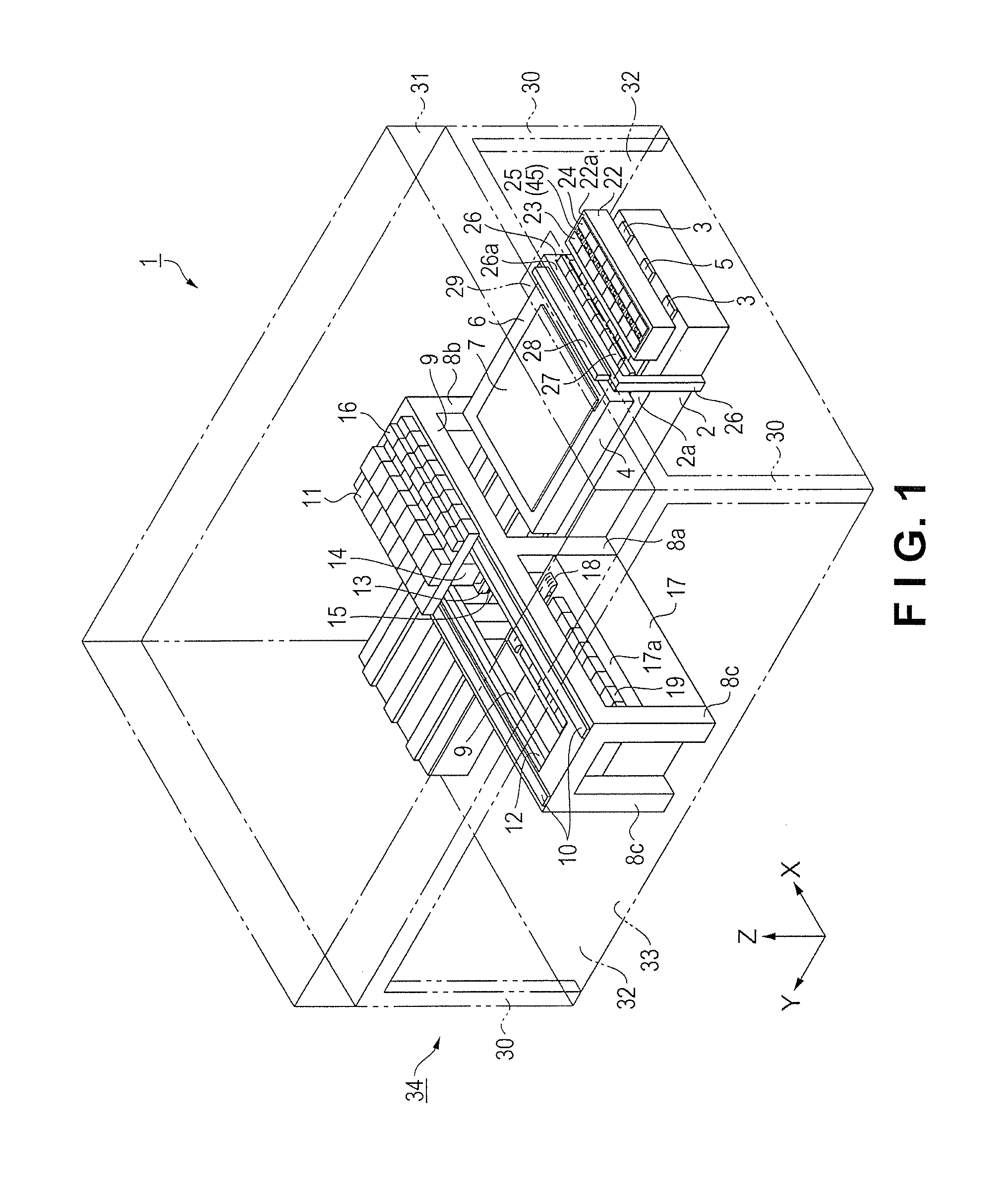
[0027]FIG. 1 is a schematic perspective view showing the configuration of the droplet discharge device. The functional liquid is discharged and sprayed by the droplet discharge device 1. The droplet discharge device 1 has a base 2 formed in the shape of a rectangular parallelepiped, as shown in FIG. 1. In the present embodiment, the longitudinal direction of the base 2 is the Y direction (one ...
second embodiment
[0104]Referring now to FIG. 11, a droplet discharge device 85 in accordance with a second embodiment will now be explained. In view of the similarity between the first and second embodiments, the parts of the second embodiment that are identical to the parts of the first embodiment will be given the same reference numerals as the parts of the first embodiment. Moreover, the descriptions of the parts of the second embodiment that are identical to the parts of the first embodiment may be omitted for the sake of brevity.
[0105]The second embodiment differs from the first embodiment in that a plurality of wind-guard covers 86 are driven separately.
[0106]Specifically, in the second embodiment, the droplet discharge device 85 has the same number of the individual wind-guard covers 86 as the number of the catch pans 45, as shown in FIG. 11. The individual wind-guard covers 86 each have a wind-guard cover drive device 87, which controls the raising and lowering of the corresponding one of th...
third embodiment
[0110]Referring now to FIG. 12, a droplet discharge device 88 in accordance with a third embodiment will now be explained. In view of the similarity between the first, second and third embodiments, the parts of the third embodiment that are identical to the parts of the first or second embodiment will be given the same reference numerals as the parts of the first or second embodiment. Moreover, the descriptions of the parts of the third embodiment that are identical to the parts of the first or second embodiment may be omitted for the sake of brevity.
[0111]The third embodiment differs from the first embodiment in that a groove 90b is formed in a support part 90 for supporting a weight measurement device 89, and the end part 47b of the wind-guard cover 47 fits into the groove 90b.
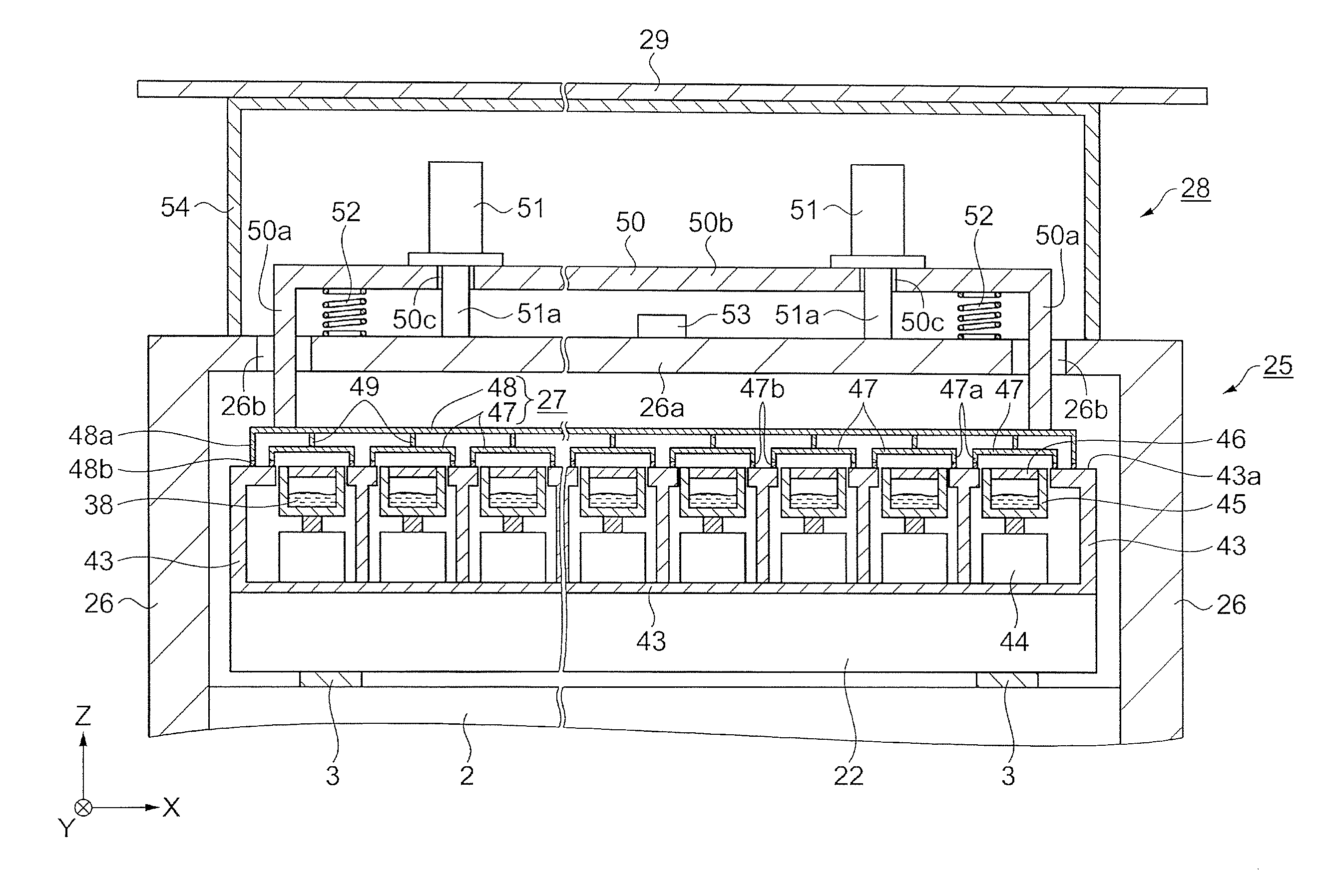
[0112]FIGS. 12(a) and 12(b) are partial schematic cross-sectional views showing the structure of the wind-guard covers. Specifically, in the present embodiment, the weight measurement device 89 of the dropl...
PUM
 Abstract
Description
Claims
Application Information