
Methods for forming injected molded parts and in-mold sensors therefor

Active Publication Date: 2011-05-05
UNIV OF MASSACHUSETTS
View PDF27 Cites 11 Cited by
  • Summary
  • Abstract
  • Description
  • Claims
  • Application Information

AI Technical Summary

Benefits of technology

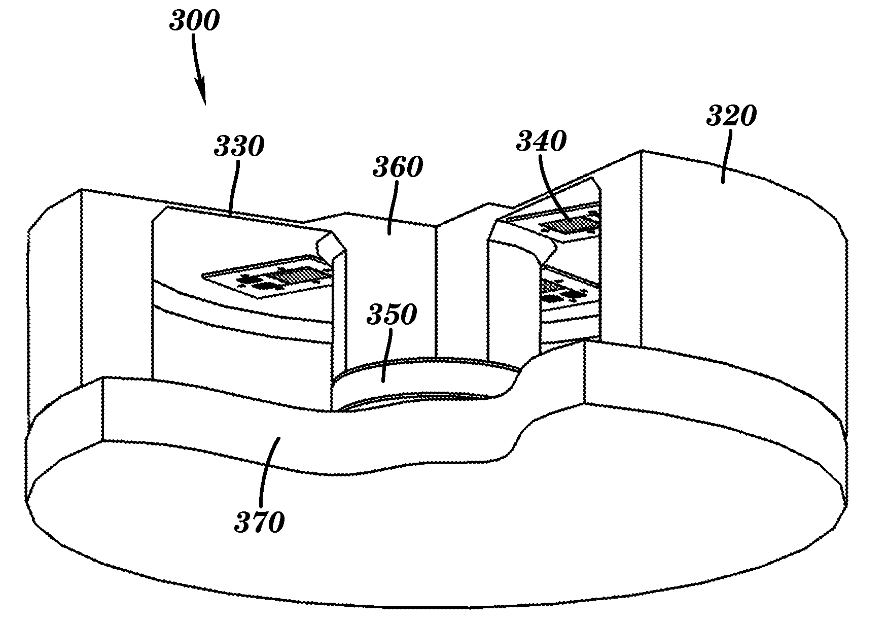
[0016]The present invention, in a fourth aspect, is directed to a system for controlling the forming of a plurality of molded parts in a cavity of a mold. The system includes a sensor for monitoring at least one of an in-mold part dimension and an in-mold shrinkage of the part based on movement of a movable pin biased to maintain an end of the movable pin in contact with the moldable material in the cavity during curing of the moldable material until the moldable material is cured, and a processor operable to control a plurality of operating parameters for forming the plurality of molded parts based on the monitored at least one of the in-mold part dimension of the part and the in-mold shrinkage of the part.
[0017]The present invention, in a fifth aspect, is directed

Problems solved by technology

As a result, tighter tolerances are possible, albeit with an uncertain amount of testing, instrumentation, and processing costs.
However, no single control strategy or system design has been universally successful, and defective components continue to be manufactured during high volume production.
Mechanistic approaches vary in complexity from relatively simple analysis of pressure-volume-temperature relations to complex thermo viscoelastic modeling of residual stress relaxation.
The size, cost, and maintenance issues associated with these designs prevent widespread adoption for in-mold shrinkage measurement.
In addition, there have been significant increases in molded part complexity due to the development and widespread implementation of design for manufacturing and assembly (DFMA) guidelines that leverage the capability of the injection molding process.

Method used


Image

  • Methods for forming injected molded parts and in-mold sensors therefor
  • Methods for forming injected molded parts and in-mold sensors therefor
  • Methods for forming injected molded parts and in-mold sensors therefor

Examples


Embodiment Construction

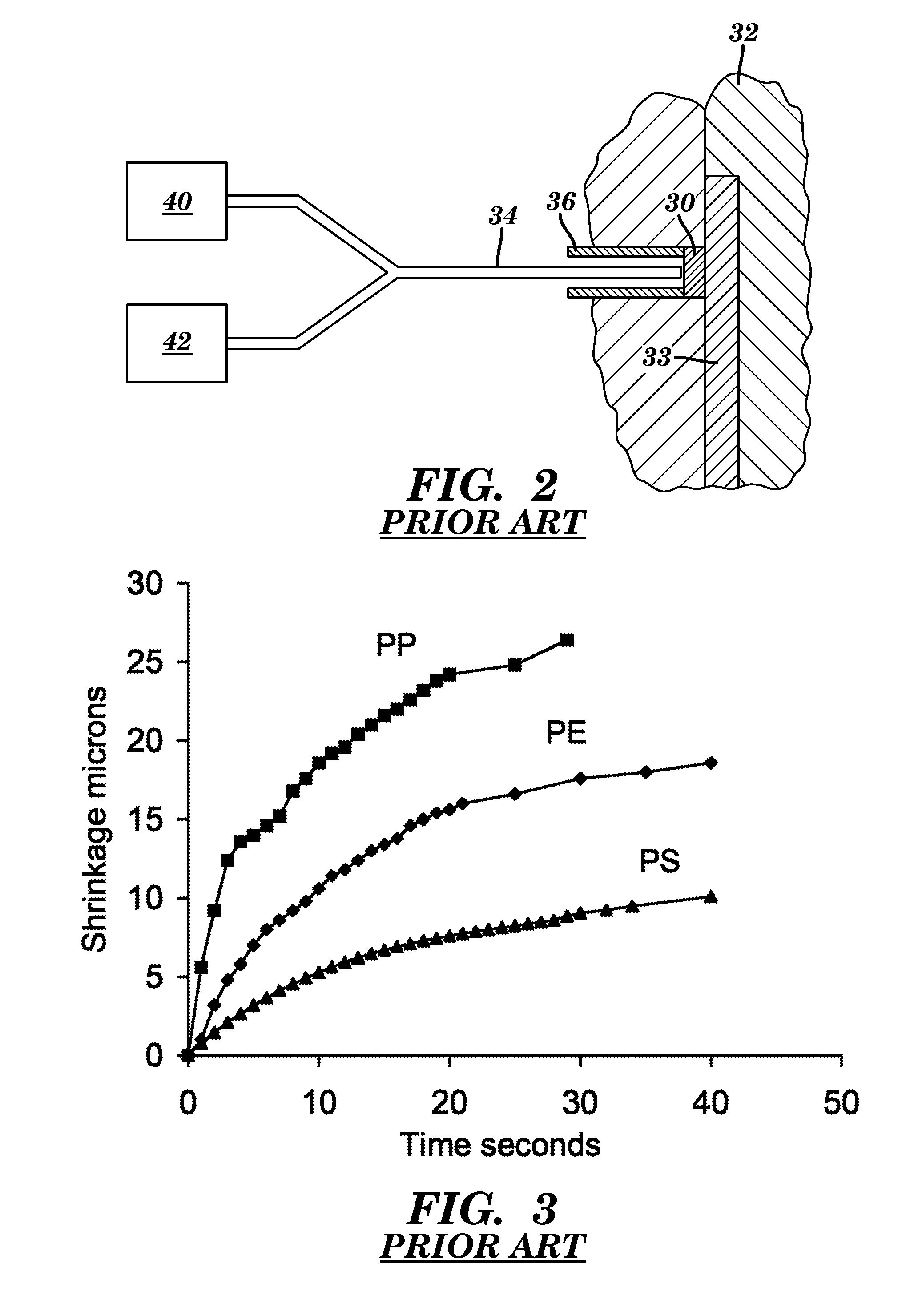
[0047]One of the challenges in the injection molding of plastic parts is the control required to produce parts with desired dimensions reproducibly. In-mold shrinkage is the major driver of final part dimensions, and it is a function of cavity pressures, mold and melt temperatures, cycle times, and material properties among other factors. Shrinkage can be very difficult to predict, and particularly, control for tight tolerance in multi-cavity operations.

[0048]While prior art sensors prove effective as process control variables, they are in fact poor estimators of the manufactured part quality and advances in machine control have not kept pace with part design requirements. Perhaps surprisingly, the final part dimensions are not precisely known during the product design and mold tooling phases. The control of shrinkage can be difficult, especially in tight tolerance and multi-cavity applications. Molding operations are greatly impaired by the lack of direct observability and controll...


PUM

PropertyMeasurementUnit
Temperatureaaaaaaaaaa
Forceaaaaaaaaaa
Pressureaaaaaaaaaa

Abstract

A method for use in forming a molded part includes providing a mold having a cavity and a movable pin, injecting a moldable material into the cavity, biasing the movable pin to maintain an end of the movable pin in contact with the moldable material in the cavity during the curing of the moldable material and until the moldable material is cured, and monitoring movement of the biased movable pin during curing of the moldable material in the mold. Also disclosed is a sensor engageable with an end of a movable pin of a mold for monitoring the forming of a moldable part, and systems employing the same.

Description

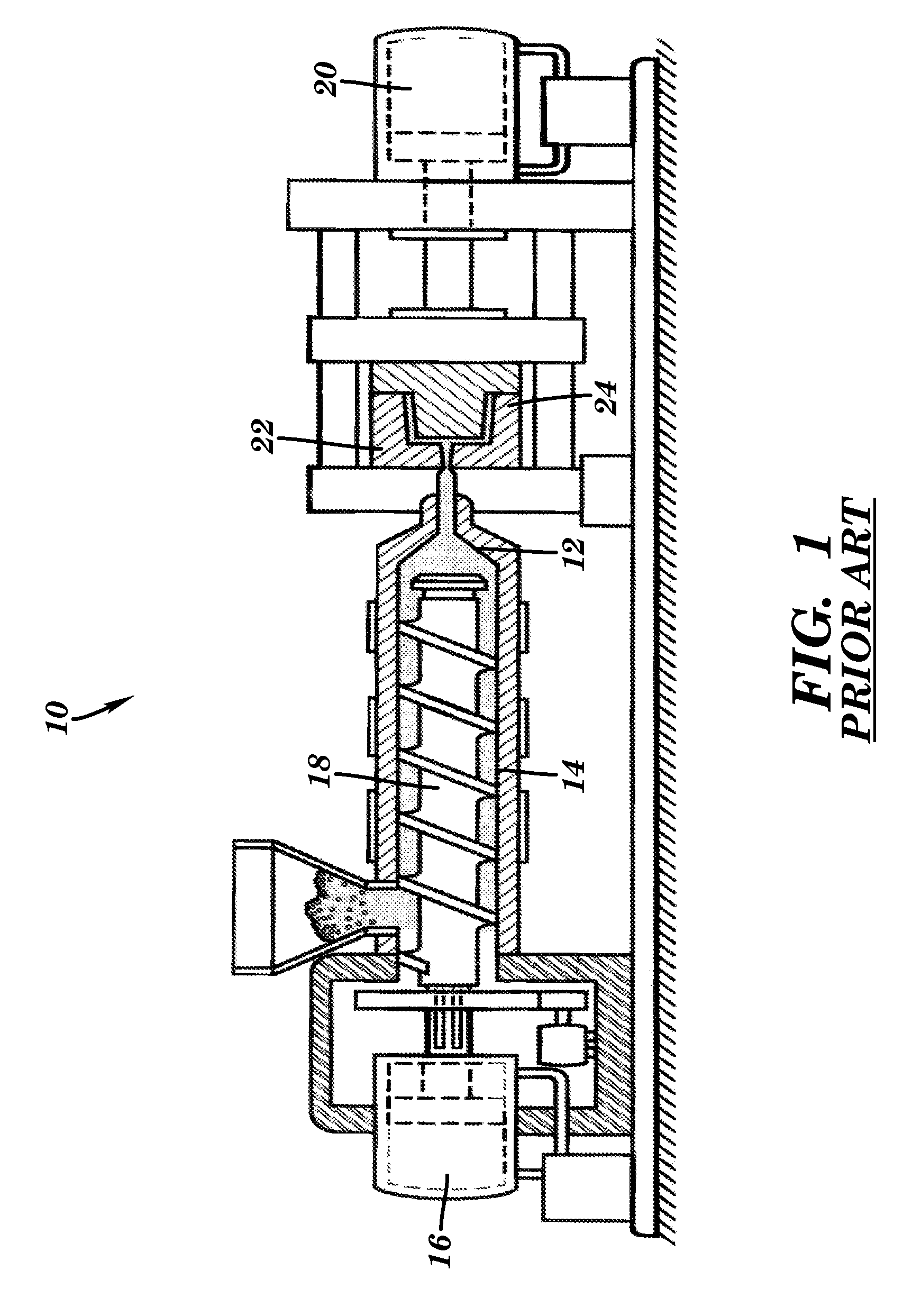
CLAIM TO PRIORITY[0001]This application claims the benefit of U.S. Provisional Application No. 61 / 044,698, filed Apr. 14, 2008, entitled “Methods For Forming Injected Molded Parts And In-Mold Sensors Therefor,” the entire subject matter of which is hereby incorporated herein by reference.FIELD OF THE INVENTION[0002]This invention relates generally to high fidelity systems for dimensional control of injection molded products, and more specifically, to sensors designed to measure in-mold part dimensions and cavity pressures, and mechanistic analyses used to predict the final molded part dimensions, perform control actions, and synthesize alternative feasible processes.BACKGROUND OF THE INVENTION[0003]Plastics manufacturing has made continuous gains in capability and competitiveness. Many industry advancements have been fueled by technological progress related to process analysis, instrumentation, and control. FIG. 1 is a prior art closed-loop injection molding machine 10 with varying ...

Claims


Application Information

Patent Timeline
IPC IPC(8): B29C45/76
CPCB29C45/76B29C2945/76006B29C2945/76103B29C2945/76257B29C2945/76381B29C2945/76933B29C2945/76391B29C2945/76414B29C2945/76585B29C2945/76892B29C2945/76384
Inventor KAZMER, DAVIDPANCHAL, RAHULJOHNSTON, STEPHEN
Owner UNIV OF MASSACHUSETTS
Learn More