Fluid pipe connection device

a technology for connecting devices and fluid pipes, which is applied in the direction of hose connections, couplings, manufacturing tools, etc., can solve the problems of inability to smoothly carry out the disassembly of pipes, and achieve the effect of easy wear and damag

Active Publication Date: 2011-05-05
JS WORLDWIDE LTD
View PDF12 Cites 24 Cited by
  • Summary
  • Abstract
  • Description
  • Claims
  • Application Information

AI Technical Summary

Benefits of technology

[0004]The invention aims at solving the problem of troublesome operation of pipe disassembly and simultaneously solving the problem that the top part of the push tooth ring is easily worn and damaged due to collision.

Problems solved by technology

The adoption of a threaded connection structure between the push tooth ring and the plug sleeve has two defects: 1) when the pipe is being disassembled, the hook spanner needs to be used for hooking the concave position of the push tooth ring to rotate in the forward direction so as to disassemble the pipe, and then the rotation in the reverse direction needs to be carried out for resetting, thereby being troublesome to operate; and 2) in order to lead the to top part of the push tooth ring to be still hooked by the hook spanner when leading the push tooth ring to go into the plug sleeve and further push the internal teeth, the top part of the push tooth ring is required to be always significantly protrudent out of the plug sleeve during the long-term using process before disassembling the pipe, and the top part of the push tooth ring is easily worn and damaged due to collision, so that the disassembly of the pipe can not be smoothly carried out.

Method used


Image

  • Fluid pipe connection device
  • Fluid pipe connection device
  • Fluid pipe connection device

Examples


Embodiment Construction

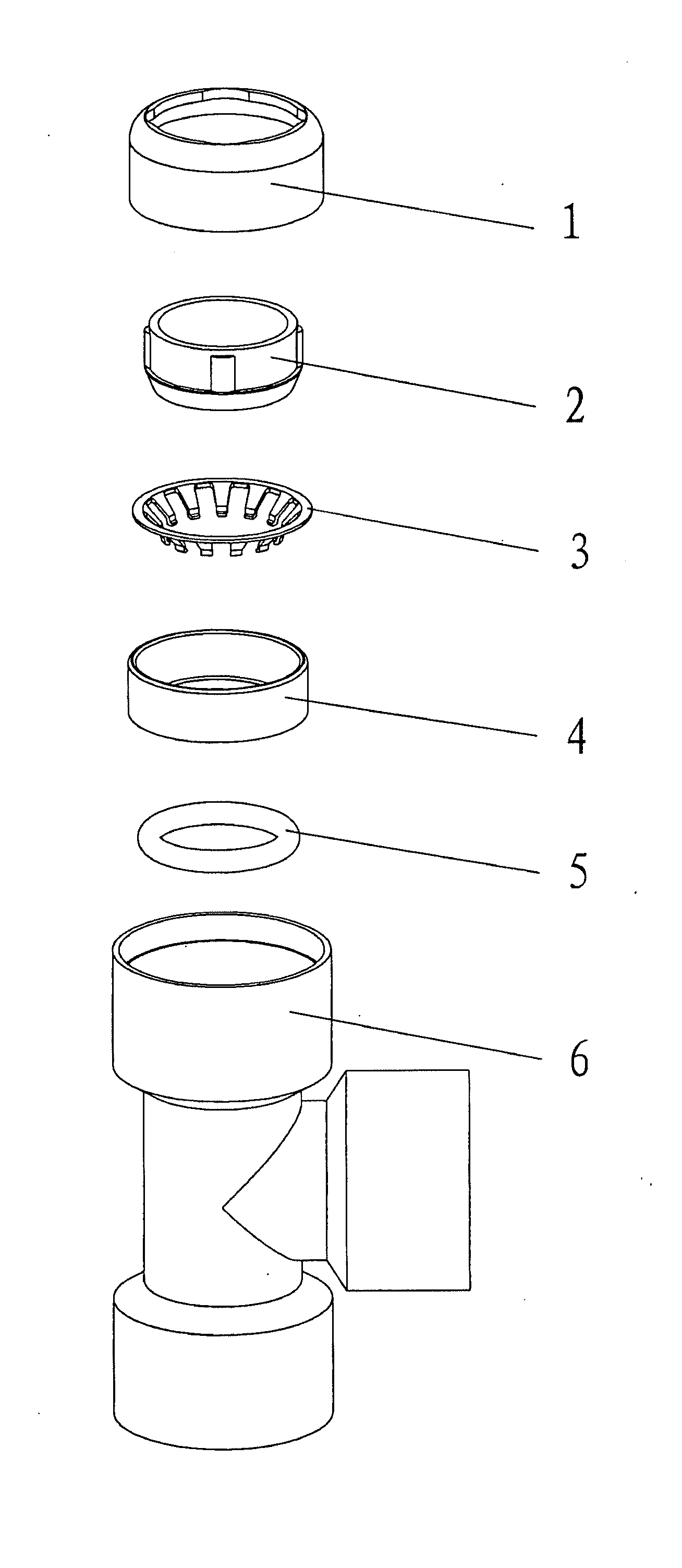
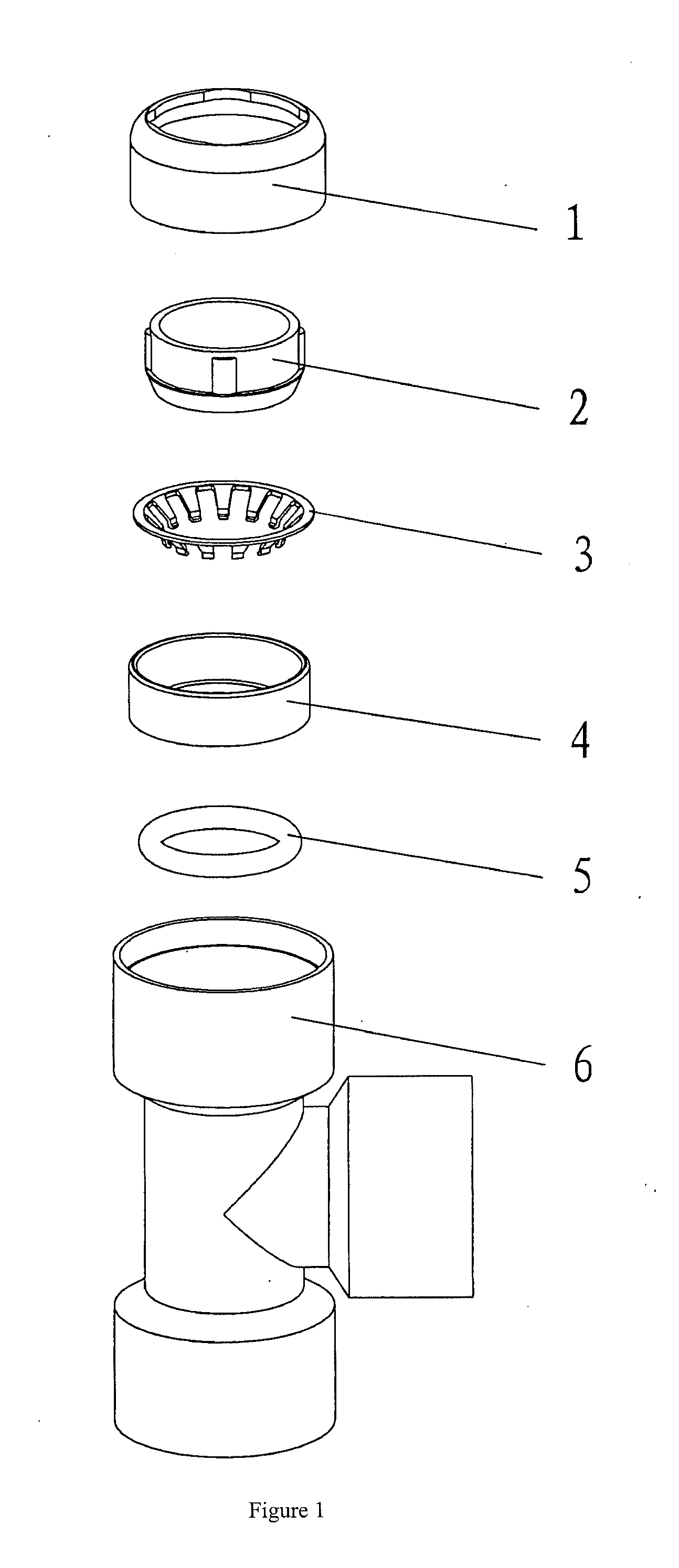
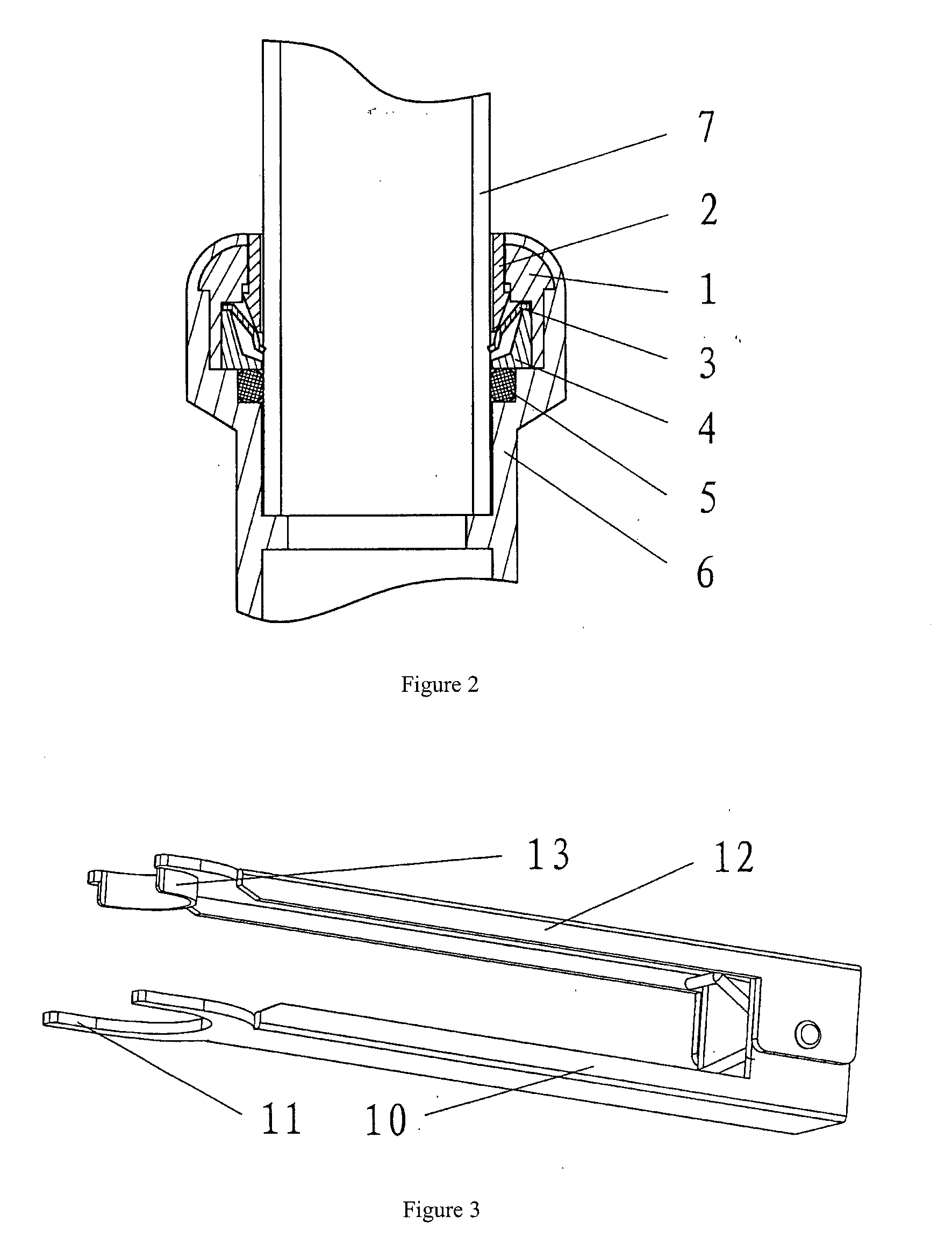
[0016]FIGS. 1 and 2 show an external sealing type fluid pipe connection device which includes a plug sleeve 1, a push tooth ring 2, an internal tooth snap ring 3, a bearing ring 4, a sealing ring 5 and a pipe joint 6. The plug sleeve 1 is placed in the pipe joint 6 and compressed by using a tool or fixedly fastened in other ways, thereby wrapping the push tooth ring 2, the internal tooth snap ring 3, the bearing ring 4, the sealing ring 5 and other parts in the pipe joint 6 and the plug sleeve 1. The internal tooth snap ring 3 is placed on the bearing ring 4, and the sealing ring 5 is arranged below the bearing ring 4. The push tooth ring 2 is in sliding fit with the plug sleeve 1. A top end of the push tooth ring 2 is basically flush with the plug sleeve 1 under the pipe connection state as shown in FIG. 2. The top end of the push tooth ring 2 can also be contracted in the plug sleeve 1.

[0017]A first pipe disassembly tool as shown in FIG. 3 is provided with a fixed handle 10 for be...


PUM

PropertyMeasurementUnit
soft textureaaaaaaaaaa
deformation elastic forceaaaaaaaaaa
axial displacementaaaaaaaaaa

Abstract

A fluid pipe connection device includes a plug sleeve fixedly fastened and mounted on a pipe joint used for mounting an internal tooth snap ring and a push tooth ring in the pipe joint and the plug sleeve. The internal tooth snap ring clamps the pipe wall after the pipe passes through the plug sleeve, the push tooth ring and the internal tooth snap ring. The push tooth ring pushes away internal teeth along the pipe insertion direction so as to lead the internal tooth snap ring to release the pipe wall before disassembling a pipe. A top end of the push tooth ring is basically flush with an exposed element or contracted in the exposed element under the pipe connection state. The exposed element is the more prominent one of the plug sleeve and the pipe joint. The invention also relates to a pipe disassembly tool.

Description

FIELD OF INVENTION[0001]The invention relates to a fluid pipe connection device and a pipe disassembly tool matched therewith.BACKGROUND OF THE INVENTION[0002]The Chinese patent 200310101202.7, which is authorized announcement No. CN1324258C, (hereinafter referred to as a reference document), records a fluid pipe connection device for guiding the flow of water or gas and other fluids (called as a water or gas pipe connection device in the reference document), which includes a pipe joint and a plug sleeve which can be fixedly fastened and mounted on the pipe joint, and the plug sleeve is sheathed outside the pipe wall after a pipe passes through the plug sleeve. An internal tooth snap ring (called as an internal tooth locking ring 3 in the reference document) and a push tooth ring (called as an opening and closing ring 2 in the reference document) are mounted in the pipe joint and the plug sleeve. When in connection, the pipe passes through the plug sleeve and the push tooth ring, th...

Claims


Application Information

Patent Timeline
Patent Type & Authority Applications(United States)
IPC IPC(8): F16L17/00B23P19/04
CPCB25B27/10Y10T29/53796F16L37/091Y10T29/53896F16L37/0915
Inventor LAI, LIN WAI
Owner JS WORLDWIDE LTD
Why Eureka
Try Eureka