LED apparatus and method for accurate lens alignment

a technology of led apparatus and lens alignment, which is applied in the manufacture of electric discharge tubes/lamps, lighting and heating apparatuses, and support devices, etc., can solve the problems of reducing light output efficiency and adding material costs to the manufacturing of led apparatus, and achieves accurate shape of outer and/or inner surfaces, high efficiency, and loss of light output and distribution

Active Publication Date: 2011-05-05
IDEAL IND LIGHTING LLC
View PDF18 Cites 79 Cited by
  • Summary
  • Abstract
  • Description
  • Claims
  • Application Information

AI Technical Summary

Benefits of technology

[0040]Still another aspect of this invention is a method for manufacturing custom high-efficiency LED lensing for LED-array modules of the type including a mounting board having a plurality of LED devices spaced from one another thereon. During manufacturing of an individual separate lens member certain high-precision technologies are used to make an accurate shape of outer and/or inner surfaces of the lens portion. This is critical in achieving high-efficiency light output and distribution. Application of some of such high-precision technologies is limited when multiple lens portions are formed together in a single-piece lensing such that each of the multiple lens portions lacks some of the desired high-efficiency characteristics. This results in a loss efficiency of light-output and distribution. The inventive method allows to achieve the high accuracy of the individually-made lens portions which are securely arranged together fo...

Problems solved by technology

Such packaging may add material costs to manufacturing LED apparatus.
The presence of the reflector in packaged LED ...

Method used


Image

  • LED apparatus and method for accurate lens alignment
  • LED apparatus and method for accurate lens alignment
  • LED apparatus and method for accurate lens alignment

Examples


Embodiment Construction

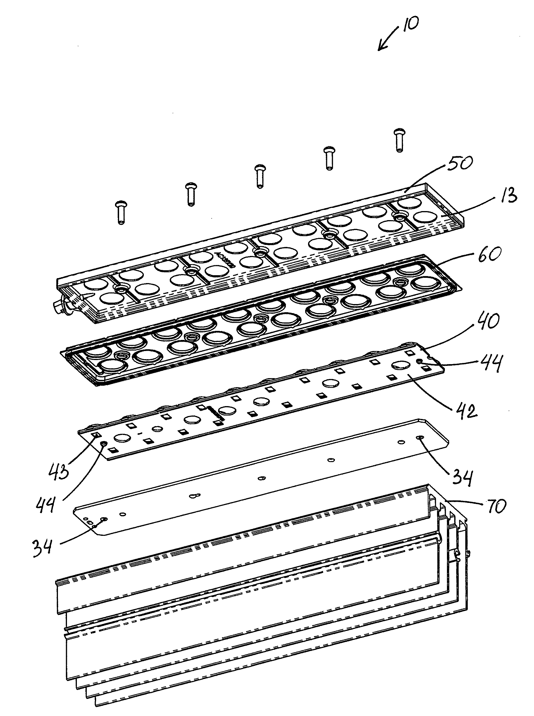
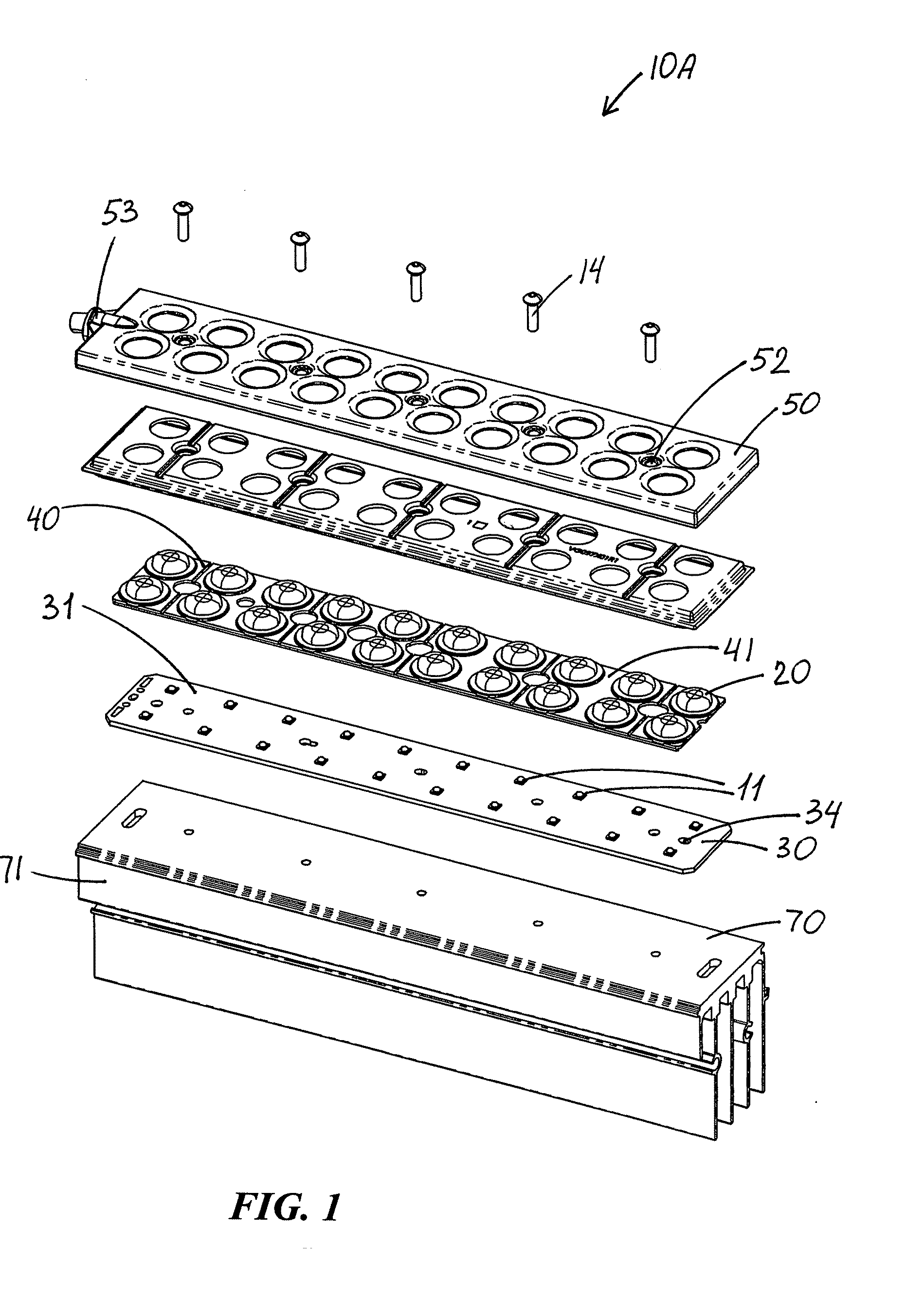
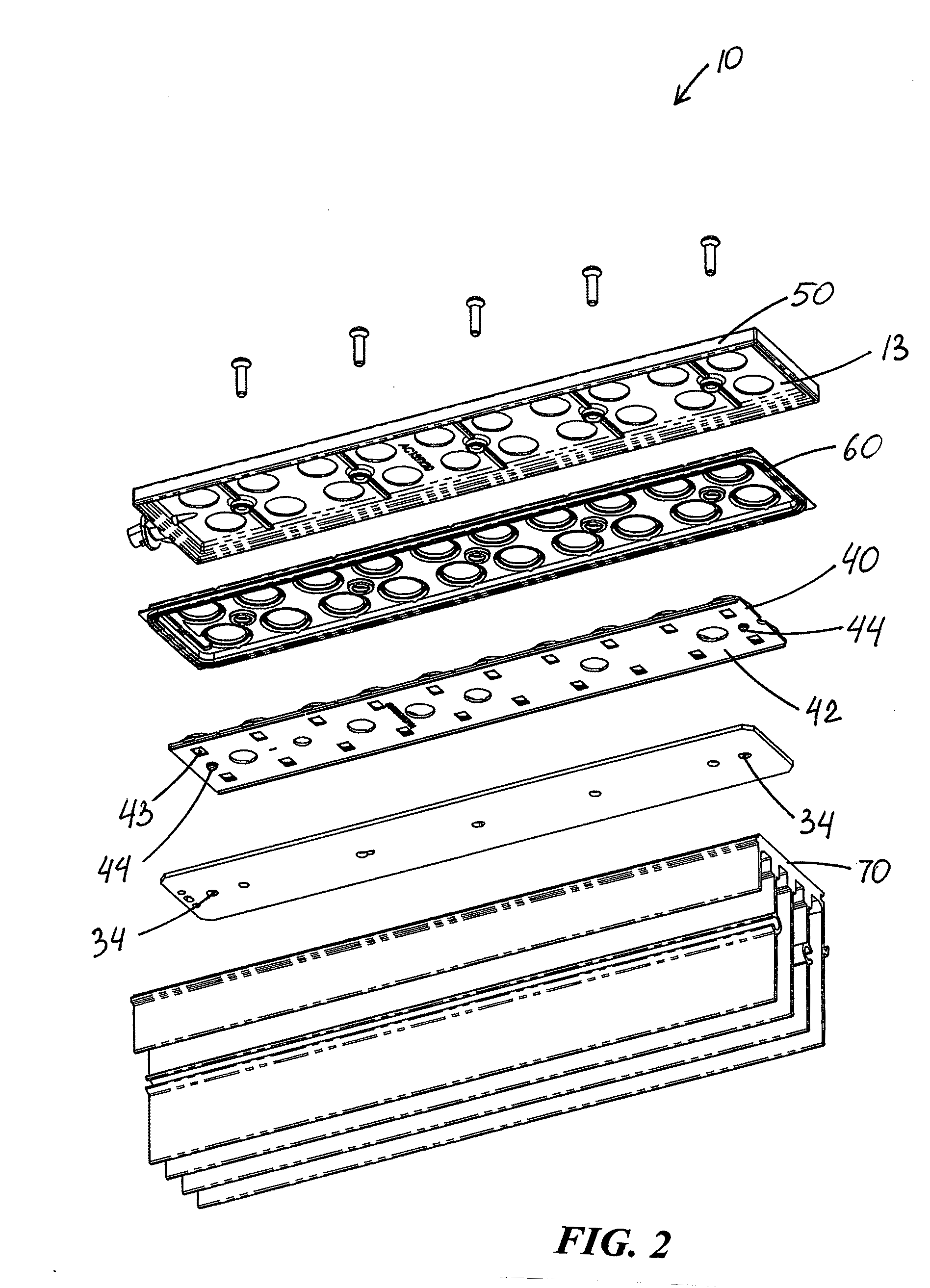
[0070]FIGS. 1-18 illustrate an improvement in LED apparatus 10 of the type having an LED device 11 defining a light-emission axis 12 and a lens member 20 positioned over LED device 11 and establishing a light path 21 therebetween. LED device 11 is on a mounting board 30 having an LED-supporting surface 31.

[0071]As best seen in FIGS. 1 and 2, LED apparatus 10 of the present invention provides an important advantage in that it utilizes very small LED devices 11 which include an LED configured for illuminating substantially white light and preferably without reflectors or substantial primary lenses.

[0072]Inventive LED apparatus 10 includes a lens-aligning member 40 having a front surface 41 and a back surface 42 and defining an aperture 43. FIGS. 3-9 best illustrate that aperture 43 is configured to receive LED device 11 therethrough such that LED device 11 protrudes beyond front surface 41. FIGS. 1 and 7-12 show that lens member 20 includes a lens portion 22 and a flange thereabout 23...


PUM


Abstract

An LED apparatus of the type including (a) a mounting board having an LED-supporting surface with an LED device thereon and (b) a lens member over the LED device establishing a light path therebetween. The inventive LED apparatus includes a lens-aligning member having front and back surfaces and defining an aperture receiving the LED device therethrough such that the LED device protrudes beyond the front surface. The lens member includes a lens portion and a flange thereabout, the flange being attached to the front surface of the lens-aligning member such that the lens portion substantially surrounds the protruding LED device. The lens-aligning member has a first mating feature which is positioned and arranged for mating engagement with a second mating feature of the mounting board, thereby accurately aligning the lens member over the LED device by accurately aligning the lens-alignment member with the mounting board. Other aspects of the invention is a method for LED-apparatus assembly and a method for manufacturing custom high-efficiency LED lensing for LED-array modules.

Description

RELATED APPLICATION[0001]This application relates to U.S. application Ser. Nos. 11 / 744,807, filed May 4, 2007, 11 / 744,422, filed on Jul. 6, 2007, and 12 / 473,017, filed on May 27, 2009. The contents of each of these applications are incorporated herein by reference.FIELD OF THE INVENTION[0002]This invention relates to lighting fixtures and, more particularly, to methods of assembling lighting fixtures of the type having LED emitters.BACKGROUND OF THE INVENTION[0003]In recent years, the use of light-emitting diodes (LEDs) for various common lighting purposes has increased, and this trend has accelerated as advances have been made in LEDs and in LED-array bearing devices, often referred to as “LED modules.” Indeed, lighting applications which have been served by fixtures using high-intensity discharge (HID) lamps and other light sources are now increasingly being to be served by LED modules. Such lighting applications include, among a good many others, roadway lighting, parking lot lig...

Claims


Application Information

Patent Timeline
IPC IPC(8): F21V1/00F21V5/00F21V29/00H01J9/24F23Q23/08
CPCF21S2/005F21V5/007F21V5/04F21V5/08F21V7/0008F21V17/005F21V29/763F21V25/12F21V31/005F21W2131/103F21Y2101/02F21Y2105/001F21S4/008F21V17/06F21S4/28F21Y2105/10F21Y2115/10
Inventor WILCOX, KURT S.GUILLIEN, WAYNESIEBERS, SCOTKAPELLUSCH, JOEL
Owner IDEAL IND LIGHTING LLC
Why Eureka
Try Eureka