

Enhanced cross correlation detection or mitigation circuits, processes, devices, receivers and systems
a cross correlation detection and mitigation circuit technology, applied in the direction of digital transmission, amplitude demodulation, instruments, etc., can solve the problems of insufficient cross correlation, cross correlation protection provided by the 1 ms pn (pseudorandom noise) codes used by gps satellites, and insufficient for such a large dynamic range, so as to increase the confidence of valid peak identification
Active Publication Date: 2011-05-05
TEXAS INSTR INC
View PDF19 Cites 76 Cited by
- Summary
- Abstract
- Description
- Claims
- Application Information
AI Technical Summary
Benefits of technology
[0019]Generally, further additional form of the invention involves a cross correlation protection system including non-zero integer KHz relative Doppler cross correlation mitigation mechanisms having outputs coupled according to a decision function for increasing confidence of a valid peak identification,
Problems solved by technology
The cross correlation protection provided by the 1 ms PN (pseudorandom noise) codes used by GPS satellites, for instance, is not sufficient for such a large dynamic range, which is problematic.
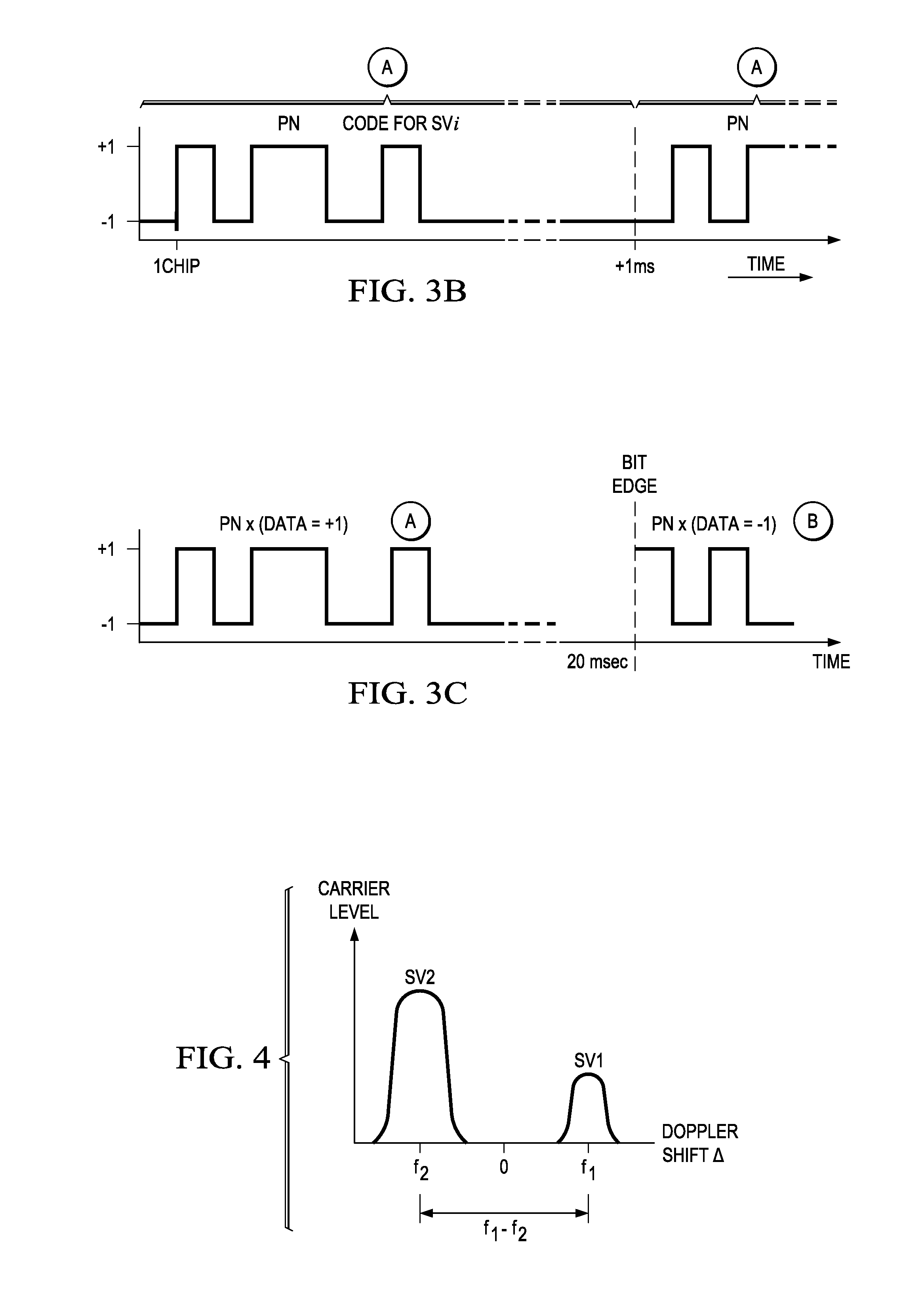
The cross correlation problem occurs mainly when the Dopplers are close by or same as each other or their Doppler difference is close to a one kilohertz (1 Khz) or a multiple of 1 KHz.
Cross correlation interference is a problem especially in GPS receivers because the PN-codes are not designed to operate in such wide power ranges.
The GPS system was not designed for such a large dynamic range of nearly 38 db.
Cross correlation mitigation techniques hitherto have been undesirably conservative or pessimistic in nature and tend to reject valid lower power satellite vehicle (SV) signals as cross correlation.
This detection approach is undesirably conservative or pessimistic in nature because the low power measurement could be a genuine or uncorrupted valid lower power peak of an actual satellite vehicle, designated SV1 here.
Limitations of such approach are first, being undesirably conservative in nature and regarding even true lower power peaks as suspect and rejecting them as if they were
Method used
View moreImage
Smart ImageViewing Examples

Examples
 PUM
 Abstract
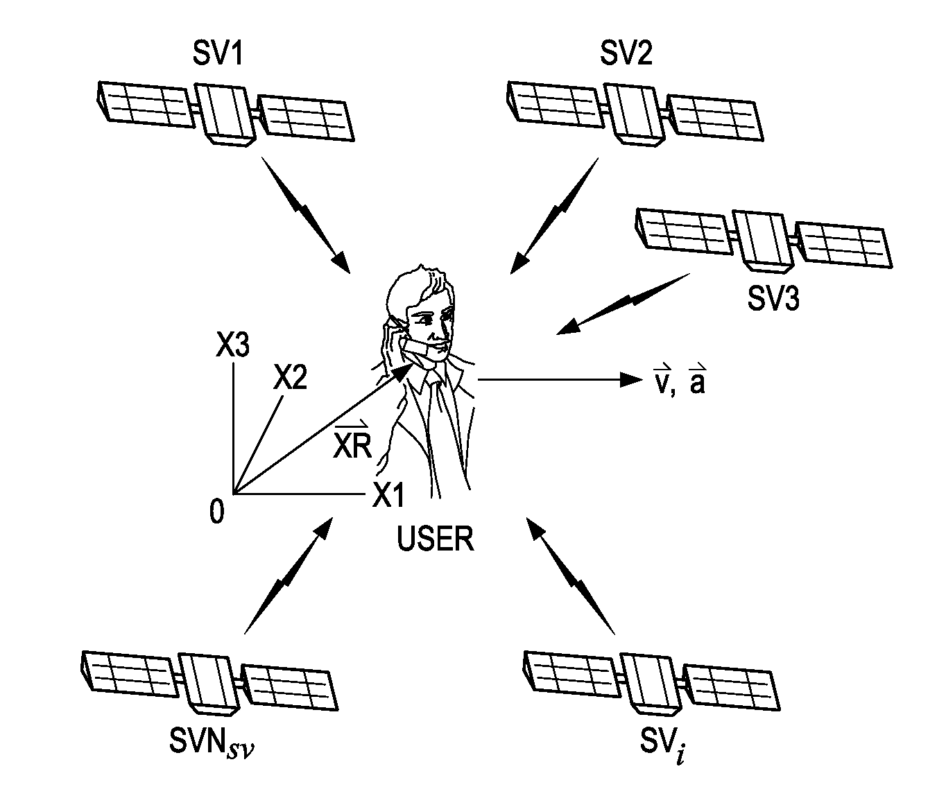
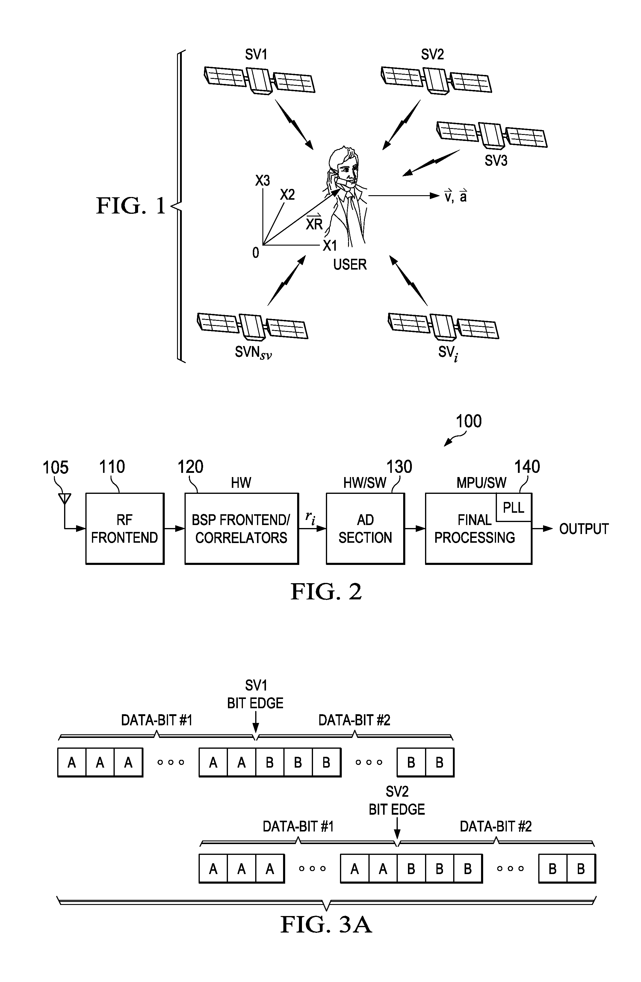
A receiver (100) is provided for signals of different signal strengths and modulated with respective pseudorandom noise (PN) codes. The receiver (100) includes a correlator circuit (120) operable to correlate the signals with a selectable locally-issued PN code having a Doppler and a code lag to produce a peak, the correlator circuit (120) being subject to cross correlation with a distinct PN code carried by least one of the signals that can produce cross correlation; and a cross correlation circuit (370, 400) operable to generate a variable comparison value related to the cross correlation as a function of values representing a Doppler difference and a code lag difference between the locally-issued PN code and the distinct PN code, and to use the variable comparison value to reject the peak as invalid from cross correlation or to pass the peak as a valid received peak.
Description
CROSS-REFERENCES TO RELATED APPLICATIONS[0001]This application is related to provisional U.S. patent application “Enhanced Cross Correlation Mitigation Techniques For Positioning Receiver” Ser. No. 61 / 257,239 (TI-67277PS), filed Nov. 2, 2009, for which priority is claimed under 35 U.S.C. 119(e) and all other applicable law, and which is incorporated herein by reference in its entirety.[0002]US published patent application 20090168843 dated Jul. 2, 2009 “Power-Saving Receiver Circuits, Systems and Processes” Ser. No. 12 / 244,060 (TI-65435), filed Oct. 2, 2008, is incorporated herein by reference in its entirety.[0003]US published patent application 20090054075 Feb. 26, 2009, “Satellite (GPS) Assisted Clock Apparatus, Circuits, Systems and Processes for Cellular Terminals on Asynchronous Networks,” Ser. No. 11 / 844,006 (TI-38194), filed Aug. 3, 2007, is also incorporated by reference herein in its entirety.STATEMENT REGARDING FEDERALLY SPONSORED RESEARCH OR DEVELOPMENT[0004]Not applicab...
Claims
Login to View More Application Information
Patent Timeline
 IPC IPC(8): H04B1/707H04L27/06
CPCG01S19/21H04B2201/70715H04B1/70755
InventorTANGUDU, JAWAHARLALRAGHUPATHY, ARUN
OwnerTEXAS INSTR INC