Eureka AIR delivers breakthrough ideas for toughest innovation challenges, trusted by R&D personnel around the world.

Machine Tool, especially Handheld Machine Tool

Inactive Publication Date: 2011-05-12
ROBERT BOSCH GMBH
View PDF15 Cites 1 Cited by
  • Summary
  • Abstract
  • Description
  • Claims
  • Application Information

AI Technical Summary

Benefits of technology

[0035]Based on a jigsaw 2 with a corresponding design to that shown in FIG. 1, FIG. 11 shows an optical arrangement 59 in which the window 30 is formed by a line-scanning sensor system 60, in the form of a camera, and a cover 61 associated with it, in which case the cover 61 for the sensor 60 bounds or can bound a closed area, which may be closed off in an air-tight manner, such that the line-scanning sensor system 60 is protected against dirt and damage, and dirt on the cover can be counteracted by all those measures which have been explained with reference to the above exemplary embodiments. I

Problems solved by technology

In the case of machine tools, in particular handheld machine tools, and in this case especially jigsaws, the user's view of the workpiece-side working area of the working tool of the machine tool is frequently restricted by handling and/or by the design.
This exacerbates the work and can also adversely affect the work results.

Method used


Image

  • Machine Tool, especially Handheld Machine Tool
  • Machine Tool, especially Handheld Machine Tool
  • Machine Tool, especially Handheld Machine Tool

Examples


Example

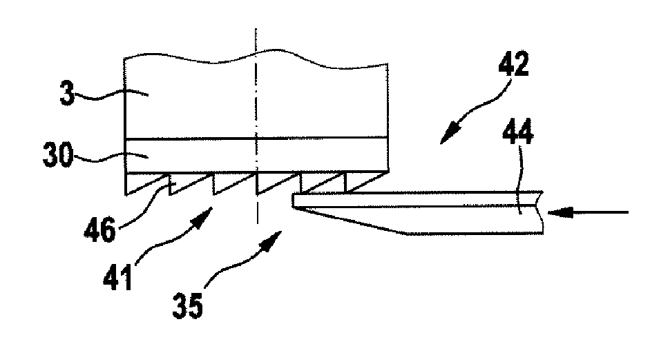
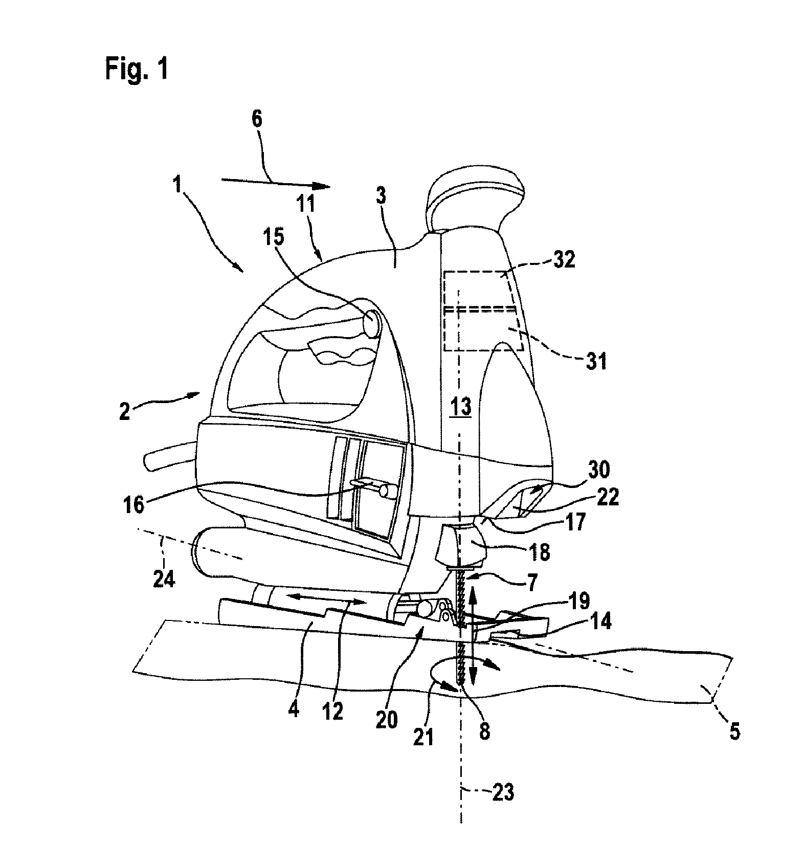
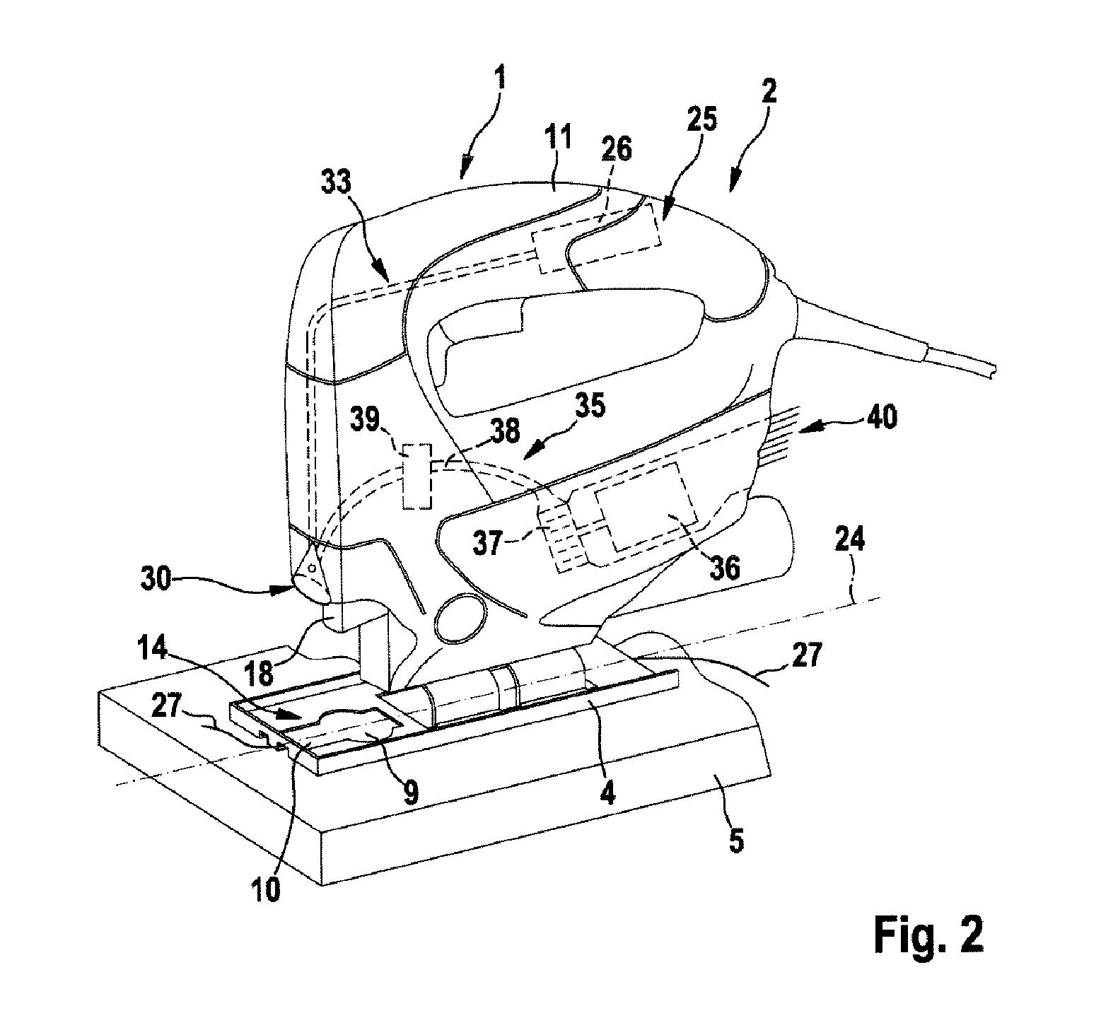
[0019]As an example of a machine tool 1, FIG. 1 shows a jigsaw 2 which is supported via a base plate 4 on a workpiece 5. The jigsaw 2 has a saw blade 8, which is driven with a reciprocating-movement in the direction of the arrow 19, as a working tool 7, in the front area of the jigsaw 2, with respect to the working direction 6, and the housing of the jigsaw 2 is annotated 3. The associated reciprocating-movement drive is arranged in the area of the housing 3 above this, whose end wall 13 ends in a step 17 in the direction of the saw blade holder 18, which step 17 overlaps the saw blade 18 on the saw blade holder 18, and in whose junction to the end wall 13 the window 30 is located, for an optical arrangement 33 which is illustrated as an example in FIG. 2. In the observation direction, the window 30 is located opposite the workpiece-side working area 9 of the saw blade 8, with a corresponding cutout 14 on the side of the baseplate4, through which the saw blade 8 passes. The optical ...


PUM

PropertyMeasurementUnit
Flow rateaaaaaaaaaa

Abstract

The invention relates to a machine tool (1), especially a machine tool designed as a handheld jigsaw (2), wherein an optical device (33; 59), the window (30) of which is associated with a protective system (35) against soiling and/or damage, is provided for the working field (9) of said machine tool and/or for a working line (27) in the detection surface (10) of said machine tool as a path specification.

Description

[0001]The invention relates to a machine tool, in particular a handheld machine tool, according to the precharacterizing clause of claim 1.PRIOR ART[0002]In the case of machine tools, in particular handheld machine tools, and in this case especially jigsaws, the user's view of the workpiece-side working area of the working tool of the machine tool is frequently restricted by handling and / or by the design. This exacerbates the work and can also adversely affect the work results. For this reason, auxiliary devices are used, for example illumination devices in order to improve at least the visibility conditions in the working area. Furthermore, observation devices are also used, which are intended to allow indirect observation of the working area.[0003]Optical arrangements such as these require a window which is aligned with the working area in the vicinity thereof, and a corresponding arrangement of this window. However, even a small window area in the vicinity of the working tool res...

Claims


Application Information

Patent Timeline
IPC IPC(8): B23D51/00B26D7/18G02B27/00
CPCB23D49/167G02B27/0006B23D59/002Y10T83/505Y10T83/828
Inventor KOEDER, THILOPLATZER, JOACHIM
Owner ROBERT BOSCH GMBH
Why Eureka
Eureka Blog
Learn More