Eureka AIR delivers breakthrough ideas for toughest innovation challenges, trusted by R&D personnel around the world.

Roof and wall cover system

Active Publication Date: 2012-07-26
SYST STORMSEAL PTY LTD
View PDF3 Cites 10 Cited by
  • Summary
  • Abstract
  • Description
  • Claims
  • Application Information

AI Technical Summary

Benefits of technology

[0039]Preferably, said vent comprises a base portion and a flexible flap adapted to cover an aperture in said base portion so as to prevent ingress of rain water.

Problems solved by technology

Roofs, as well as walls, are susceptible to damage from high winds, rain or hail.
Tiled roofs for example may have a considerable area of tiles either damaged from hail impact, or dislodged completely as the result of high intensity storms.
Shingled roofs are liable to be similarly damaged, and even metal sheeted roofs may suffer partial or total removal of one or more sheets.
Damage to roofs and walls may also be caused by the impact of falling trees, large branches, or other objects made airborne under high wind conditions.
One disadvantage of this method of temporary covering is the difficulty of adequately securing a tarpaulin to the roof or walls so that they remain very vulnerable to dislodgement should high winds prevail or recur and often require continuing attention and adjustment.
Moreover, they are heavy and awkward to position, posing occupational health and safety issues.
A further disadvantage is that they are expensive to acquire and bulky to store, and if the many roofs are damaged in one storm event, the number of tarpaulins available may be inadequate.
A disadvantage of this construction technique is that during this period the timber of the structure, which may even include timber or particle board flooring, is liable to deterioration from water and sun.
A further disadvantage of this sequence of construction is that, if rain intervenes at the time further internal work is scheduled, the lack of roof covering may cause considerable delay and financial loss.
Rolls of film are heavy and in practice the manipulation of a roll of film and the edge taping required on even an intact roof surface is extremely difficult, if not dangerous and is completely impractical for application to the roof framing of an uncompleted building.
This moisture can cause unwanted structural movement in framework constructed from kiln dried timber.
Because of the slippery nature of the wrap material and difficulties in managing said wrap in windy conditions it is often extremely awkward or even dangerous to work at elevated locations.
Also areas of slack or looseness can arise when the preformed sheet is nailed or stapled to the structure.
This results in air pockets which may detract from the insulating and sealing properties of the wrap.
Removal of such material, for example during renovations, repair or for health risk reasons, provides hazards from loose asbestos flakes and fibres escaping into the environment.

Method used


Image

  • Roof and wall cover system
  • Roof and wall cover system
  • Roof and wall cover system

Examples


first preferred embodiment

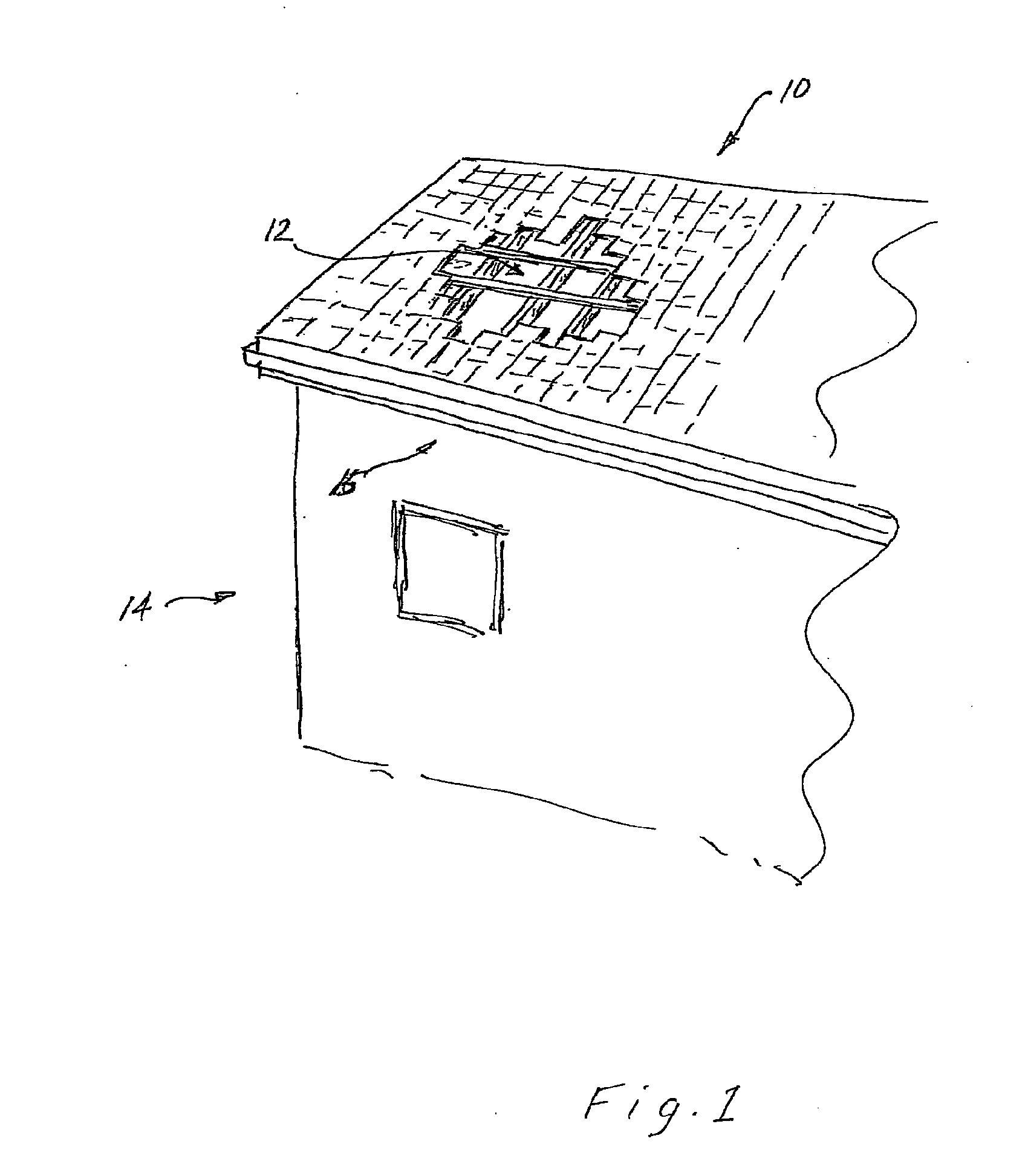
[0091]With reference now to FIG. 1, typical damage to a tiled roof 10 of a building 12 may include the loss of a number of tiles 12 due to a high wind shear event, leaving the building 14 open to the ingress of water. Water ingress may also occur if tiles are cracked for example from heavy hail impact or falling trees or branches. Emergency temporary repair is provided by the roof cover system of the invention by applying the above described film over that portion of the roof which has sustained damage.

[0092]If required, sharp edges protruding from the roof surface may first be covered with suitable wadding and adhesive tape to prevent possible tearing of the film during application.

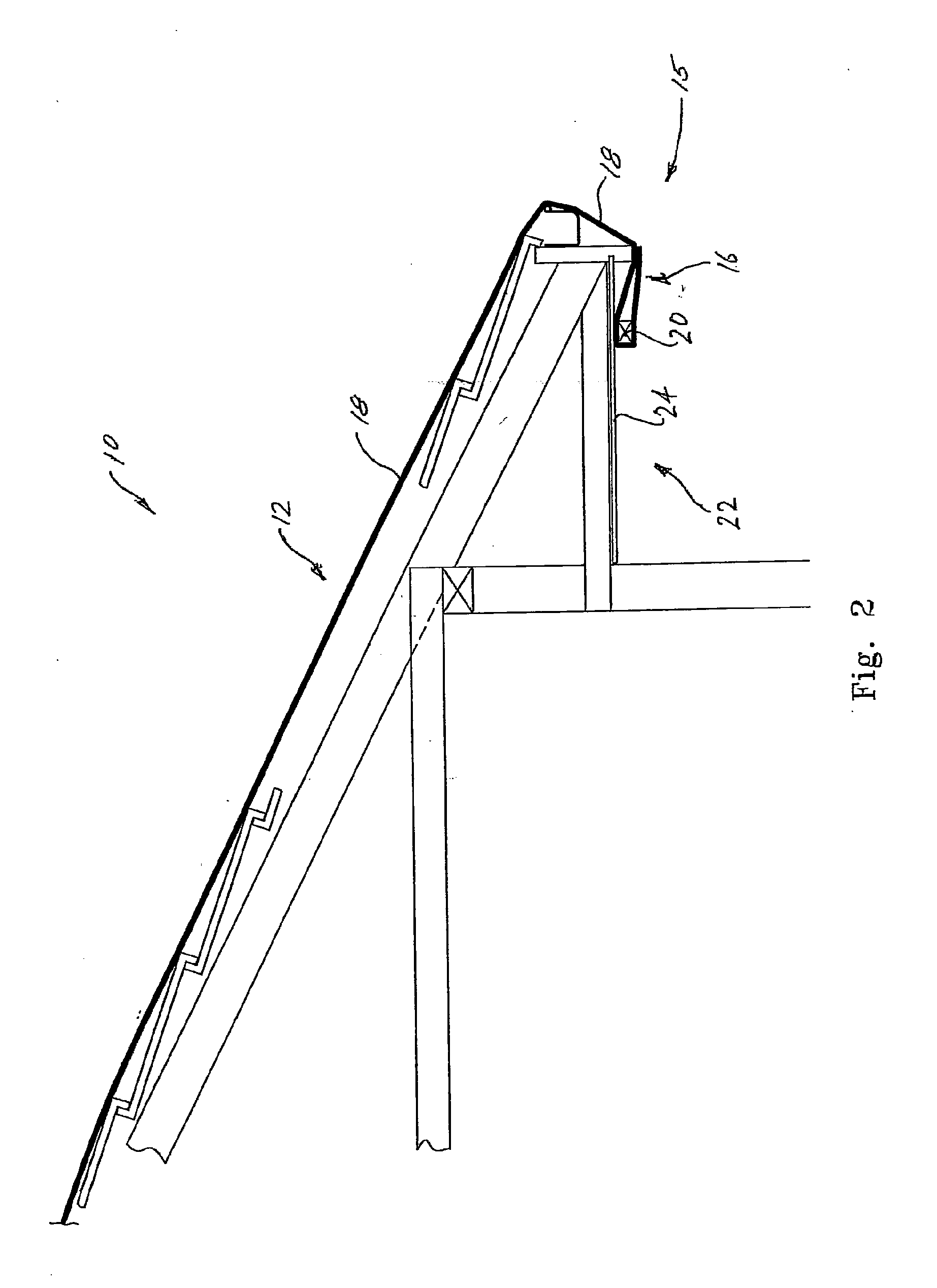
[0093]The extent of roof to be covered is measured and the most suitable available width roll of the heat shrinkable film selected. Film is cut to one or more lengths sufficient to extend from one edge of the roof to an opposite edge. With reference to FIG. 2, a trailing edge of a length of film is mecha...

second preferred embodiment

[0099]In a second preferred embodiment of the invention, a damaged section of a roof to be temporarily protected prior to permanent repair, is again covered by a heat shrinkable film. In this embodiment however, the method of application is different.

[0100]Instead of attempting to apply individual lengths of film, attaching a length at a first end to the eaves at one side of the roof, stretching the length over the roof to be attached at the eaves at the opposite side, and taping the edges of adjoining lengths of film together, the method of this embodiment, with reference to FIG. 5 is as follows:[0101](a) the location of the damaged section 12 of roof 10 is assessed in relation to the nearest opposing edges of the roof,[0102](b) the length of film required to extend between the opposing roof edges is estimated, allowing for overhang and fixing requirements,[0103](c) the width of the damaged area is ascertained and the number of lengths of the available film required to cover and ov...

third preferred embodiment

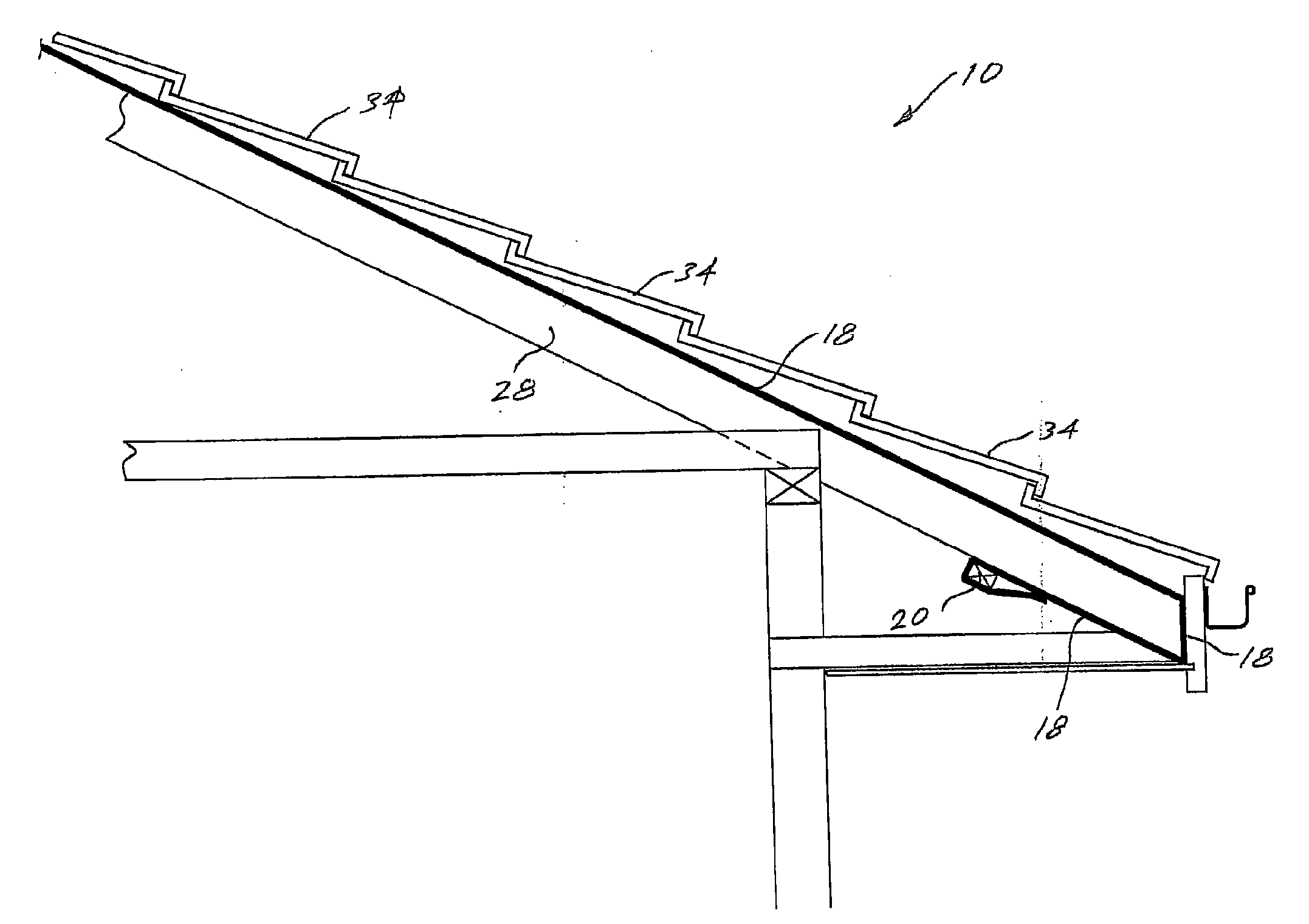
[0108]In a third preferred embodiment of the invention, a heat shrinkable film may be applied to the roof framing of an uncompleted building. In this embodiment as shown in FIG. 3, the heat shrinkable film 18 is applied after the roof framing is complete but preferably prior to the attachment of facia boards.

[0109]In this embodiment also, lengths of film are prepared from suitable width rolls sufficient to stretch from one side of the roof to an opposite side. In this case the trailing and leading edges of the length of film are preferably attached by means of battens 20 fixed to the underside of the outer ends 26 of rafters 28, that is between the outer ends of the rafters 28 and the wall frame 30.

[0110]The heat shrinkable film 18 in this embodiment, is provided with a heat reflecting upper surface 32 so that the film 18 forms a permanent sarking layer beneath the roofing cladding, either tiles 34, as shown in FIG. 4, or metal sheeting. Thus in this embodiment the heat shrinkable f...


PUM

PropertyMeasurementUnit
Lengthaaaaaaaaaa
Volumeaaaaaaaaaa
Areaaaaaaaaaaa

Abstract

A covering of a damaged or uncompleted building; the covering including a film of heat shrinkable material stretched over damaged or uncompleted portions of the building; the film formed as a sheet comprising an assembly of lengths of the heat shrinkable material applied to surfaces of the building.

Description

[0001]The present invention relates to protective covering of roofs and walls of a building and, more particularly, to the covering of damaged or under construction roofs, as well as the covering of walls of buildings.BACKGROUND[0002]Roofs, as well as walls, are susceptible to damage from high winds, rain or hail. Tiled roofs for example may have a considerable area of tiles either damaged from hail impact, or dislodged completely as the result of high intensity storms. Shingled roofs are liable to be similarly damaged, and even metal sheeted roofs may suffer partial or total removal of one or more sheets. Damage to roofs and walls may also be caused by the impact of falling trees, large branches, or other objects made airborne under high wind conditions.[0003]Storm or impact damage cannot usually be immediately repaired so that to prevent further or potential damage to the interior of the building, temporary covering must be provided. Typically canvas (or similar material) tarpauli...

Claims


Application Information

Patent Timeline
IPC IPC(8): B32B37/14B32B37/06B32B43/00B32B38/04
CPCE04D5/06E04D13/17E04D5/147E04D5/12E04D12/002E04G21/28E04G2021/248B29C66/1122E04D5/00
Inventor LENNOX, MATTHEWBURGE, RODNEYFARROW, ADAM
Owner SYST STORMSEAL PTY LTD
Why Eureka
Eureka Blog
Learn More