Eureka AIR delivers breakthrough ideas for toughest innovation challenges, trusted by R&D personnel around the world.

Right-angled coaxial cable connector

Active Publication Date: 2008-11-27
PPC BROADBAND INC +1
View PDF3 Cites 24 Cited by
  • Summary
  • Abstract
  • Description
  • Claims
  • Application Information

AI Technical Summary

Benefits of technology

[0017]In some embodiments, the connector includes a seal disposed

Problems solved by technology

Crimping braided outer conductors is problematic.
This crimp is not considered highly reliable.
There are typically large voids in the interface allowing for corrosive degradation of the contact surfaces.
Finally, the connection allows relative movement between all 3 components, which results in a very poor, noisy electrical connection.
Often times these standardized connector and tooling systems are used to manufacture CATV jumper cables in large quantities, causing unnecessary expense to be incurred in the manufacture of CATV jumper assemblies.
The construction of right angle connectors is typically more complex than the construction of straight connectors because of the difficulty of maintaining mechanical and electrical characteristics of the coaxial structure around a right angle bend.
Additionally, in right angle connectors, it is difficult to achieve comparable electrical performance to that of a straight connector due to interruptions along the center conductor path.
However, it is known in the art that the passage of moisture inside the F-connector can lead to corrosion, increased contact resistance, reduced signal strength, and excessive RF leakage from the connector.
However, in this case, the O-ring is contacted by the threaded post and can be degraded by such contact.
In addition, the creation of the rearwardly-directed collar within the coupling nut increases manufacturing costs because the coupling nut must be machined from both ends.
The continuous drag applied by such O-rings to the coupling nut is a nuisance to service technicians, as compared with indoor-type free-spinning coupling nuts because it is more difficult to rotate the coupling nut as it is being hand-tightened over the threaded post.

Method used


Image

  • Right-angled coaxial cable connector
  • Right-angled coaxial cable connector
  • Right-angled coaxial cable connector

Examples


Embodiment Construction

[0032]Reference will now be made in detail to the present preferred embodiment(s) of the invention, examples of which are illustrated in the accompanying drawings. Whenever possible, the same reference numerals will be used throughout the drawings to refer to the same or like parts.

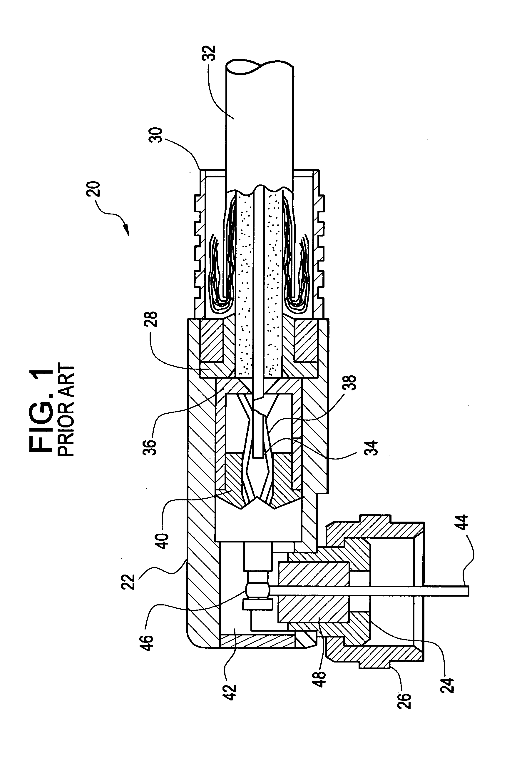
[0033]Referring to FIG. 1, a prior art right-angled connector 20 is illustrated. The right-angled connector 20 has a main body 22, into which at one end a nut retainer 24 and coupling nut 26 are press fit. At a second end, the main body 22 has a post 28 and a crimp ring 30 to engage a coaxial cable 32. The central conductor 34 of the coaxial cable 32 passes through an insulator 36 before engaging a flat spring contact 38 that is disposed in a second insulator 40. An electrical conductor 42 is electrically connected to the flat spring contact 38 at one end and soldered to a pin 44 at the other end at solder joint 46. The pin 44 passes through another insulator 48 for connection to a threaded port. Typicall...


PUM


Abstract

A right-angled coaxial cable connector for coupling an end of a coaxial cable to a terminal is disclosed, the right-angled connector includes fewer components and better impedance characteristics. The right-angled coaxial cable connector includes a main body into which a coaxial cable is inserted, a retainer inserted into the main body, and a coupler for connecting the connector to a terminal. The right-angled coaxial cable connector also has a seal disposed between the retainer and the coupler.

Description

BACKGROUND OF THE INVENTION[0001]1. Field of the Invention[0002]The present invention relates generally to right-angled coaxial cable connectors, and particularly to right-angled coaxial cable connectors that have fewer components and may be sealed for outside use.[0003]2. Technical Background[0004]Coaxial cable connectors such as F-connectors are used to attach coaxial cables to another object such as an appliance or junction having a terminal adapted to engage the connector. The coaxial cable typically includes a center conductor surrounded by a dielectric, in turn surrounded by a conductive grounding foil and / or braid; the conductive grounding arrangement is itself surrounded by a protective outer jacket. The F-connector is secured over the prepared end of the jacketed coaxial cable by use of a crimp or compression tool specifically designed to actuate the F-connector. Once secured to the coaxial cable, the F-connector is then capable of transferring signals by engaging a threade...

Claims


Application Information

Patent Timeline
IPC IPC(8): H01R9/05
CPCH01R9/0518H01R13/025H01R13/5202H01R13/622H01R24/54H01R2103/00
Inventor BURRIS, DONALD ANDREWLUTZ, WILLIAM BERNARD
Owner PPC BROADBAND INC
Why Eureka
Eureka Blog
Learn More