
Printer

Active Publication Date: 2011-05-12
SEIKO EPSON CORP
View PDF10 Cites 3 Cited by
  • Summary
  • Abstract
  • Description
  • Claims
  • Application Information

AI Technical Summary

Benefits of technology

[0019]The platen support mechanism according to this aspect of the invention has a platen positioning mechanism that positions the platen frame in a specific posture at four locations when at the closed position, that is, both sides of the front and both sides of the back of the platen frame in the direction in which the platen frame opens. The platen frame is therefore always positioned to the closed position in a specific posture regardless of any play in the platen support mechanism. As a result, because the posture of the platen in the printing position is always controlled to a specific posture, a constant gap can be assured between all parts of the platen surface and the print head. The gap between the recording paper conveyed over the platen surface and the print head is therefore constant, and print quality can be maintained. In addition, because the platen frame is controlled to a specific posture in the closed position, there is no interference between parts on the platen frame and the print head or other parts.

Problems solved by technology

A problem with these platen support mechanisms that use a linkage mechanism is that play develops in the joints between the links over time.
As a result, when the cover is closed and the platen is positioned to the printing position, play in the platen support mechanism may result in the platen or platen frame not being set to the desired specific posture.
In addition, if the platen frame is not supported in the specified position when the platen is positioned to the printing position, parts on the platen frame may interfere with the print head, for example, and cause other problems.
However, because this positioning method cannot control the inclination of the platen frame in the front-back direction of the printer when positioning the platen, the platen frame is not supported in the specified posture and the platen becomes tilted in the front-back direction of the printer when play develops in the platen support mechanism.

Method used


Image

  • Printer
  • Printer
  • Printer

Examples


Embodiment Construction

[0036]A preferred embodiment of an inkjet roll paper printer according to the present invention is described below with reference to the accompanying figures.

[0037]General Configuration of a Roll Paper Printer

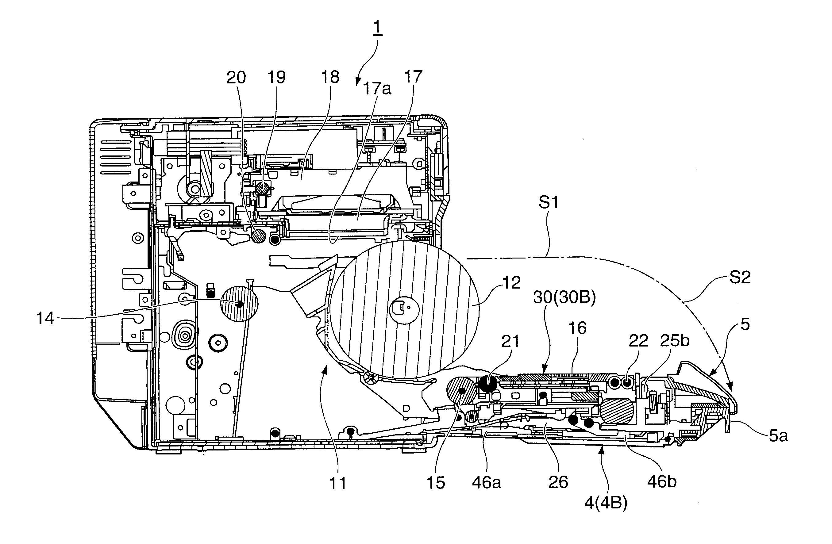
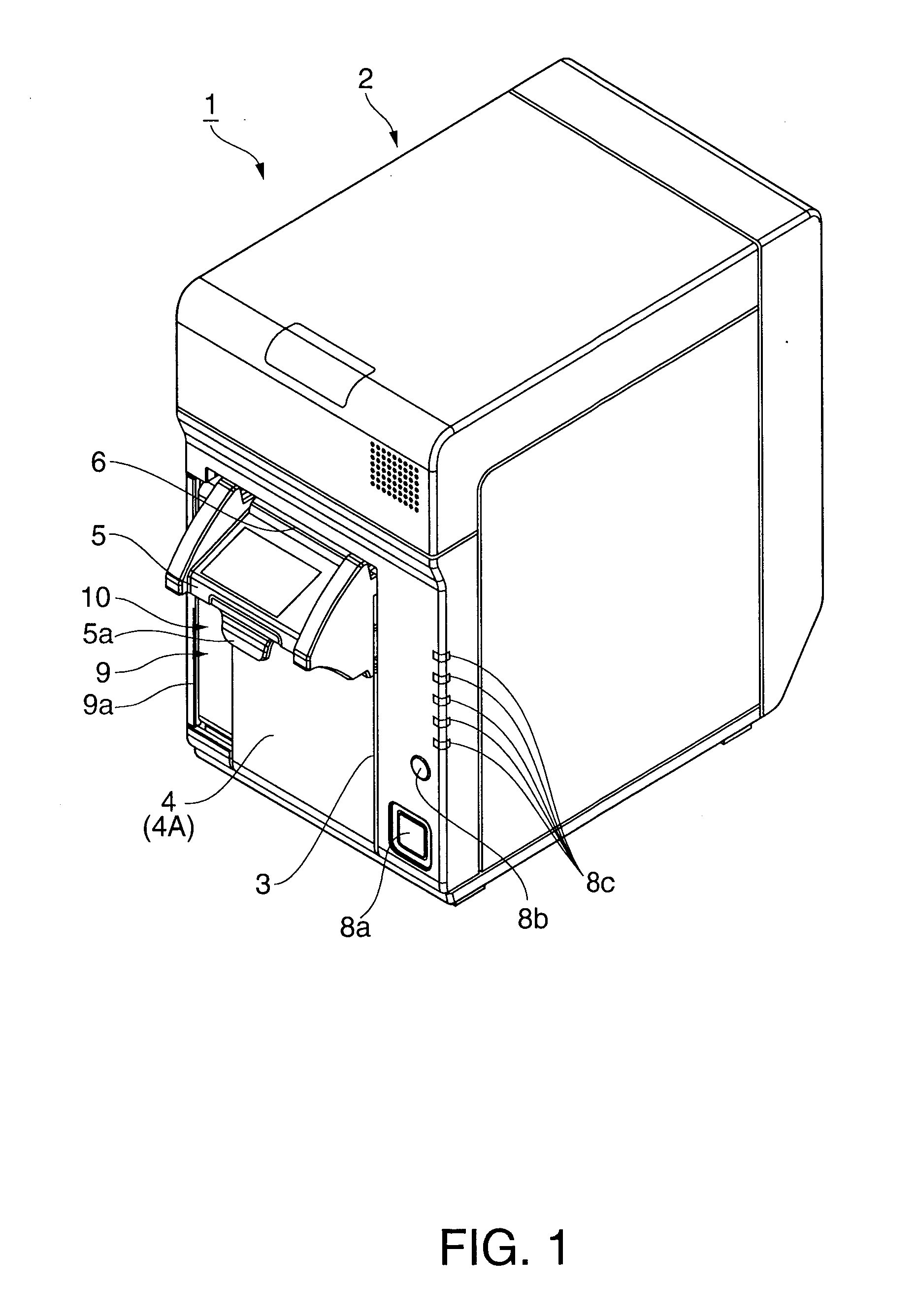
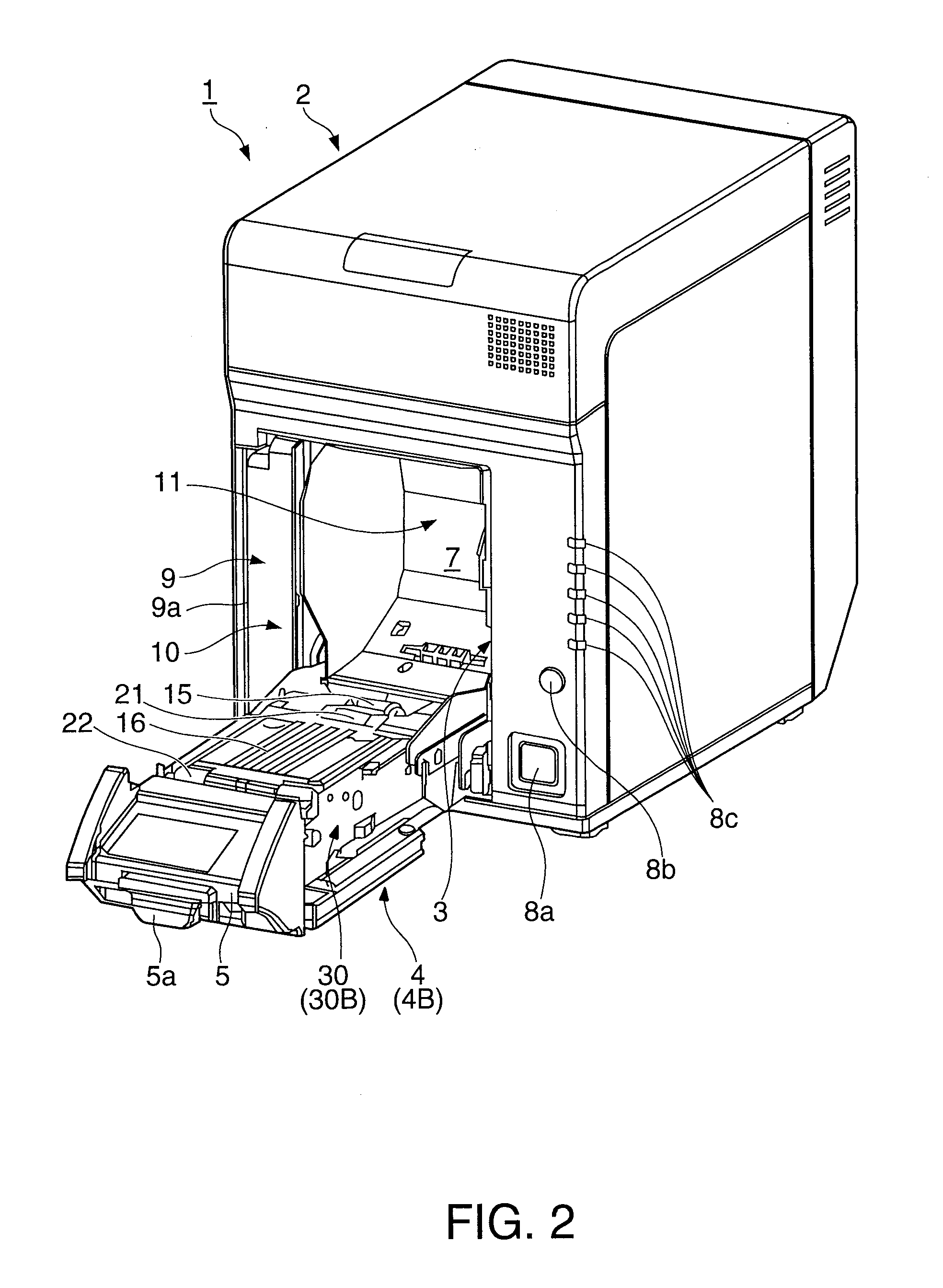
[0038]The roll paper printer 1 (referred to below as simply a printer) shown in FIG. 1 and FIG. 2 uses plural colors of ink to print in color on a web of recording paper that is delivered from a paper roll. The printer 1 has a generally box-like rectangular case 2 with an opening 3 in the middle front part of the case 2 for loading roll paper. The opening 3 is opened and closed by a cover 4. A recording paper discharge guide 5 is disposed at the top end of the cover 4, and when the cover 4 is closed (is in closed position 4A) a recording paper exit 6 is formed between the discharge guide 5 and the top edge of the opening 3 in the printer case 2.

[0039]An operating tab 5a is attached protruding down from a position at the front bottom side of the discharge guide 5. When this oper...


PUM


Abstract

A platen support mechanism that movably supports a platen unit to which a platen is attached has a platen positioning mechanism that positions the platen unit in a specific posture at four locations, bosses that protrude from both sides at the front in the front-back direction of the printer, and shaft ends that protrude from both sides at the back in the front-back direction of the printer. The platen unit is thereby positioned in a specific posture at the closed position regardless of play in the platen support mechanism. As a result, the platen is positioned to the printing position in a specific posture with a constant gap to the nozzle surface of the print head.

Description

BACKGROUND[0001]1. Technical Field[0002]The present invention relates to a printer that can move a platen that defines the printing position where a print head prints on a recording medium to a position removed from the printing position so that the recording medium transportation path is open at the printing position. More particularly, the invention relates to a printer that can position a platen movably supported by a platen support mechanism to the printing position in a specific posture.[0003]2. Related Art[0004]When loading roll paper in a roll paper printer, the cover of the roll paper compartment must be opened, the roll paper loaded, and the recording paper must be pulled from the roll and threaded through the recording paper transportation path passed the printing position of the print head. To simplify loading the recording paper, the platen, which determines the printing position, may be configured to move with the cover so that when the cover opens the platen separates ...

Claims


Application Information

Patent Timeline
IPC IPC(8): B41F13/24
CPCB41J15/042B41J11/04
Inventor INOUE, NOBUHIRO
Owner SEIKO EPSON CORP
Learn More