
Sheet feed assembly defining curved and straight feed path

a feed path and assembly technology, applied in the field of feed sheets of materials, can solve the problems of paper jamming, printing artefacts, unsatisfactory print artefacts,

Inactive Publication Date: 2010-09-09
ZAMTEC
View PDF2 Cites 6 Cited by
  • Summary
  • Abstract
  • Description
  • Claims
  • Application Information

AI Technical Summary

Benefits of technology

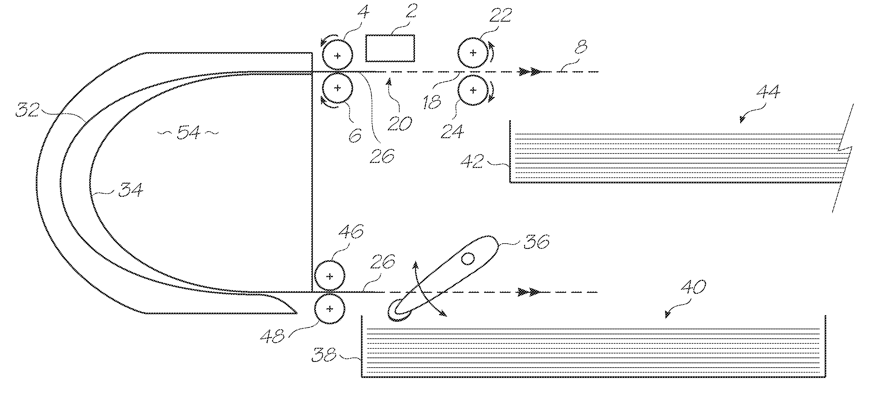
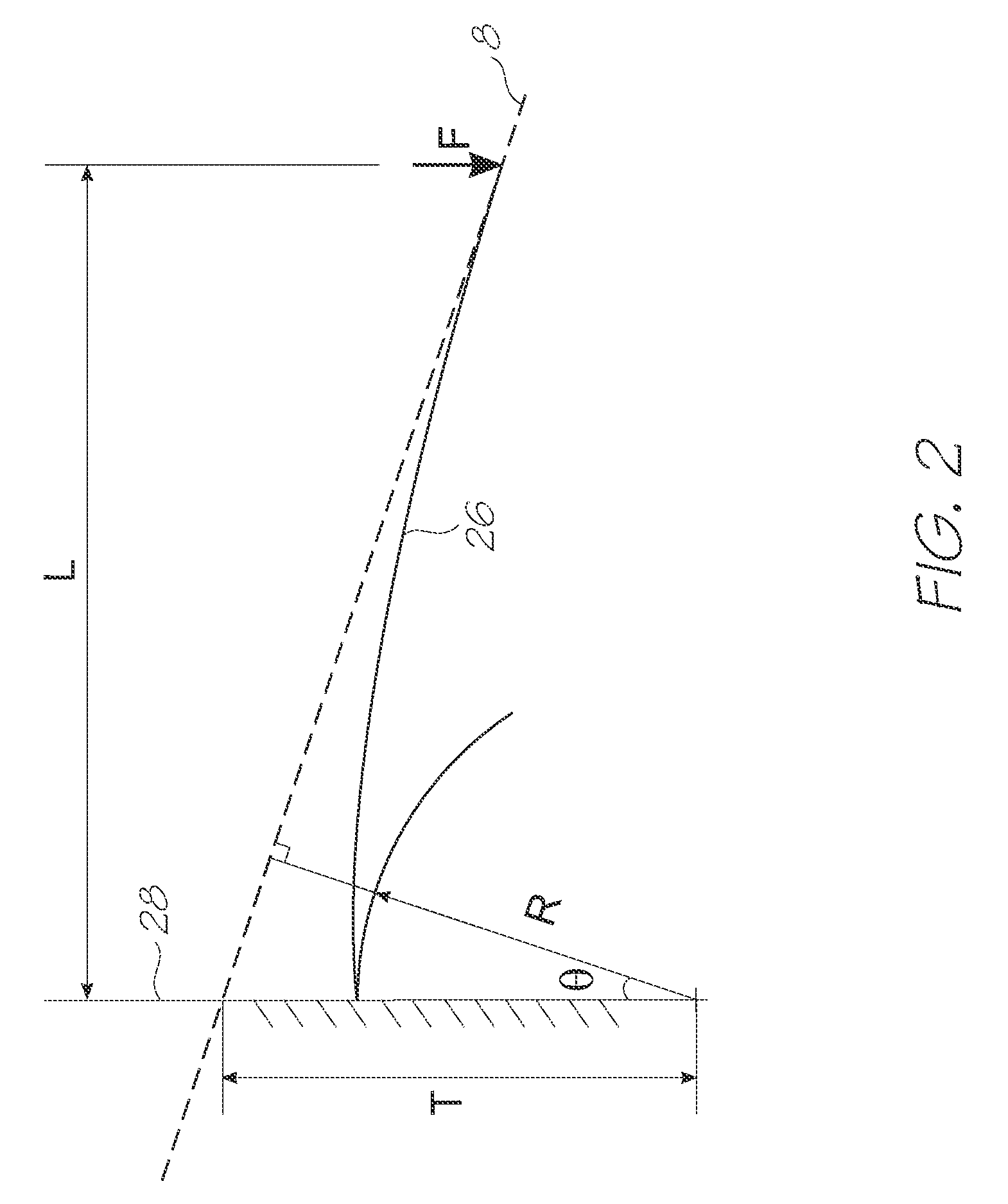
[0019]By transitioning to the straight section of the feed path at a point where the sheet inherently has zero bending moment as it passes along the feed path, the leading edge and the trailing edge has no driving mechanism to deviate from the paper path. The unconstrained leading and trailing edges follow the straight feed path like the constrained intermediate portions of the sheet. In this way, the printing gap between the nozzles and the surface of the media sheet remains constant.

Problems solved by technology

This can lead to undesirable print artefacts.
Even minute steps cause the paper to jam during threading and can cause print artefacts as the trailing edge flicks on passing.
However, it is not physically possible to apply such a step in the moment.
If the feed path is curved, it is exceedingly difficult to bend the extreme leading edge into the curved shape.
However, at a distance extremely close to the edge, the moment arm (i.e. the distance to the point where force is applied) is not long enough to generate the bending moment necessary for the sheet to flex into the curved shape defined by the guides.
This gives the leading edge a tendency to ‘chisel’ into the guide surface because it is not conforming to the curve.
Feeding sheets of paper through a printer is an example where jams, or ‘paper cockle’, in the sheet feed system are a common problem.
At these points of transition in the feed path, the sheet material is prone to deviate from the nominal or ideal path.
If the sheet is subject to a surface treatment such as the coatings on high quality photo papers, this deflection from the nominal feed path can be especially detrimental.
Varying the flight time of the ink droplets will result in visible artefacts in the resulting print.

Method used


Image

  • Sheet feed assembly defining curved and straight feed path
  • Sheet feed assembly defining curved and straight feed path
  • Sheet feed assembly defining curved and straight feed path

Examples


Embodiment Construction

Sheet Feed Chute Conforming to Shape of Bowed Sheet

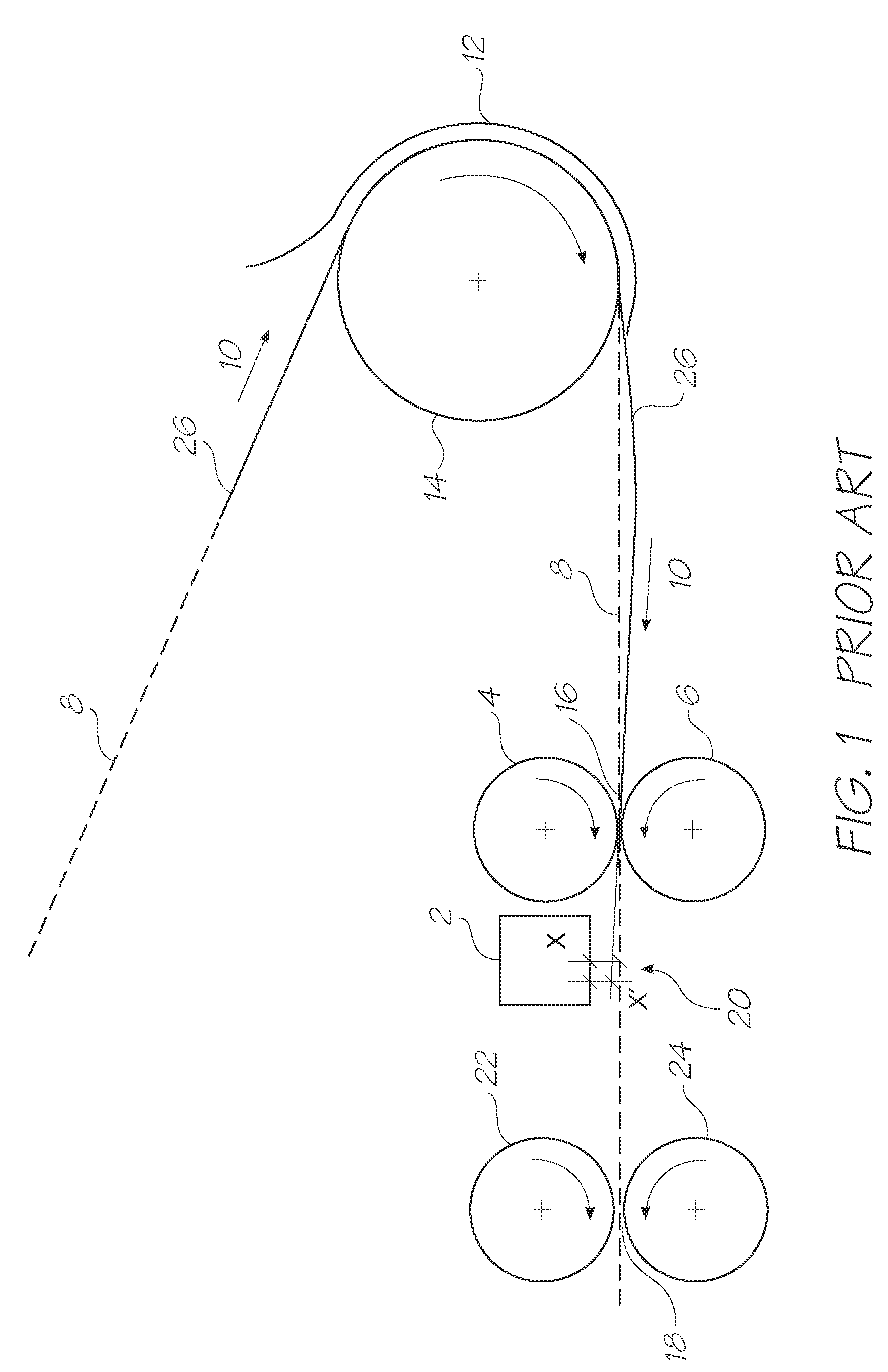
[0037]Referring to FIG. 1, a sheet feed assembly is shown feeding a sheet 26 of media substrate past a printhead 2. The feed path 8 is extends around an idler roller 14 and through the nip 16 of input drive rollers 4 and 6. The input drive rollers drive the sheet 26 past the printhead 2 and into the nip 18 of the exit rollers 22 and 24.

[0038]The inherent bending stiffness in the sheet 26 causes the leading edge to deviate away from the feed path 8 as it leaves the idler roller 14 and the guiding shroud 12. The input drive rollers 4 and 6 draw the sheet into the nip 16 and therefore back on to the feed path 8. However, the input drive rollers 4 and 6 are mounted so that the opposing pinch force from each roller are normal to the straight part of the feed path 8. This does nothing to redirect the sheet back to the feed path.

[0039]The leading edge of the sheet 26 continues to deviate as it crosses the printzone 20 of the feed path 8. T...


PUM


Abstract

A sheet feed assembly for feeding sheets of material having a known bending stiffness through a device with low friction. The sheet feeding assembly has feed path structures for defining a feed path, the feed path having a first point with a first radius of curvature, a second point with a second radius of curvature and a transition section extending between the first point and the second point. The transition section defines conforms to a shape adopted by one of the sheets of material extending from the first point where it has a curvature of the first radius, to the second point where it has a curvature of the second radius.

Description

FIELD OF THE INVENTION[0001]The present invention relates to feeding sheets of material along a feed path that has curved sections that transition into a straight section or other, differently curved sections. In particular, the invention relates to feeding sheets of paper through an inkjet printer.BACKGROUND OF THE INVENTION[0002]At first glance, a observer may conclude that there is relative freedom in the shape a paper feed path may take, however there are some general rules which must be obeyed for a sheet of paper to be able to conform to a paper guide. If the paper cannot conform to the shape of the guide, it is not actually being “guided”. This can lead to undesirable print artefacts.[0003]First (and most obviously): the path must not have any step jumps in it. Even minute steps cause the paper to jam during threading and can cause print artefacts as the trailing edge flicks on passing. The paper cannot conform to a step jump. In mathematical terms, the path must be continuou...

Claims


Application Information

Patent Timeline
Patent Type & Authority Applications(United States)
IPC IPC(8): B65H5/06
CPCB65H5/062B65H5/36B65H2404/6111B65H2511/14B65H2515/81B65H2557/24B65H2557/242B65H2220/02B65H2220/01
Inventor JENSEN, DAVID WILLIAM
Owner ZAMTEC
Learn More