Force sensor and motor-driven parking brake apparatus using the same

a technology of force sensor and parking brake, which is applied in the direction of braking system, apparatus for force/torque/work measurement, instruments, etc., can solve the problems of inability to accurately detect the moment at which the above-mentioned force is completed, and the force acting on the parking braking becomes substantially zero, so as to achieve accurate detection

Inactive Publication Date: 2008-10-28
ADVICS CO LTD
View PDF12 Cites 6 Cited by
  • Summary
  • Abstract
  • Description
  • Claims
  • Application Information

AI Technical Summary

Benefits of technology

[0009]The present invention has been accomplished in order to solve the problems in conventional force sensors, and an object of the present invention is to provide a force sensor capable of accurately detecting a time at which release of force is completed (i.e, a time at which acting force becomes substantially zero).
[0013]Incidentally, in the force sensor according to the present invention, when the force is released, after the amount of elastic deformation of the main spring becomes substantially zero, the return movement of the first member with respect to the second member is stopped by means of the preload imparted by the sub spring, so that the relative displacement between the magnet and the electrical element becomes zero, and the output voltage of the electrical element stops changing. Such an operation is performed in a similar manner even after the dimension of the main spring as measured along the direction of elastic deformation varies because of permanent set of the main spring. Accordingly, a point in time at which release of the above-mentioned force is completed (a point in time at which the force becomes substantially zero) can be accurately detected not only at the beginning of use of the force sensor, but also in intermediate and late stages of use thereof, through an operation of detecting a point in time at which the output voltage of the electrical element stops changing.
[0014]When the force sensor according to the present invention is implemented, a guide and an urging member are preferably provided so as to maintain a substantially constant clearance between the magnet and the electrical element in a direction generally perpendicular to the direction of relative displacement between the magnet and the electrical element. In this force sensor, the clearance between the magnet and the electrical element as measured in the direction substantially perpendicular to the direction of relative displacement between the magnet and the electrical element is maintained generally constant by means of the guide and the urging member. Therefore, the output voltage of the electrical element stably changes in accordance with the above-mentioned force. Accordingly, the detection accuracy of the force sensor can be improved.
[0016]In the motor-driven parking brake apparatus, at the time of release of the parking brake, a point in time at which the force acting on the parking brake becomes substantially zero can be accurately detected by use of the force sensor, irrespective of permanent set of the main spring in the force sensor. Therefore, excessive release of the parking brake can be prevented through an operation of stopping the rotation of the electric motor in the reverse direction when the force acting on the parking brake becomes substantially zero.

Problems solved by technology

Therefore, although at the beginning of actual use of the sensor the point in time at which release of the above-mentioned force is completed can be detected accurately, in an intermediate or late stage of use, the point in time at which release of the above-mentioned force is completed cannot be detected accurately.
Moreover, in the motor-driven parking brake apparatus using a force sensor disclosed in the above-mentioned publications, even when proper setting is performed at the beginning of use, because of generation of permanent set of the main spring, the sensor becomes unable to accurately detect a time at which the force acting on the parking braking becomes substantially zero, possibly raising various problems in relation to control of operation of the electric motor.

Method used


Image

  • Force sensor and motor-driven parking brake apparatus using the same
  • Force sensor and motor-driven parking brake apparatus using the same
  • Force sensor and motor-driven parking brake apparatus using the same

Examples


Embodiment Construction

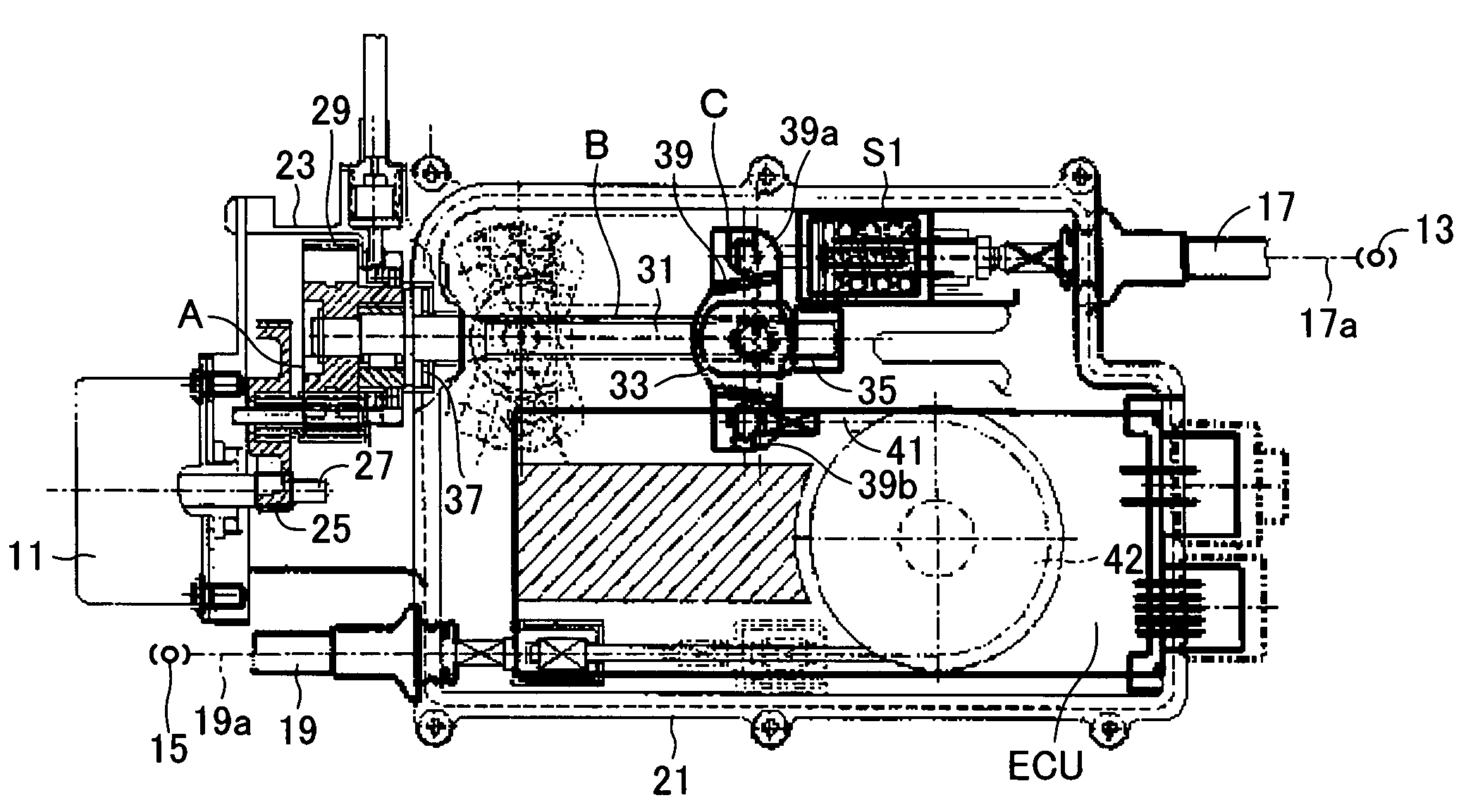
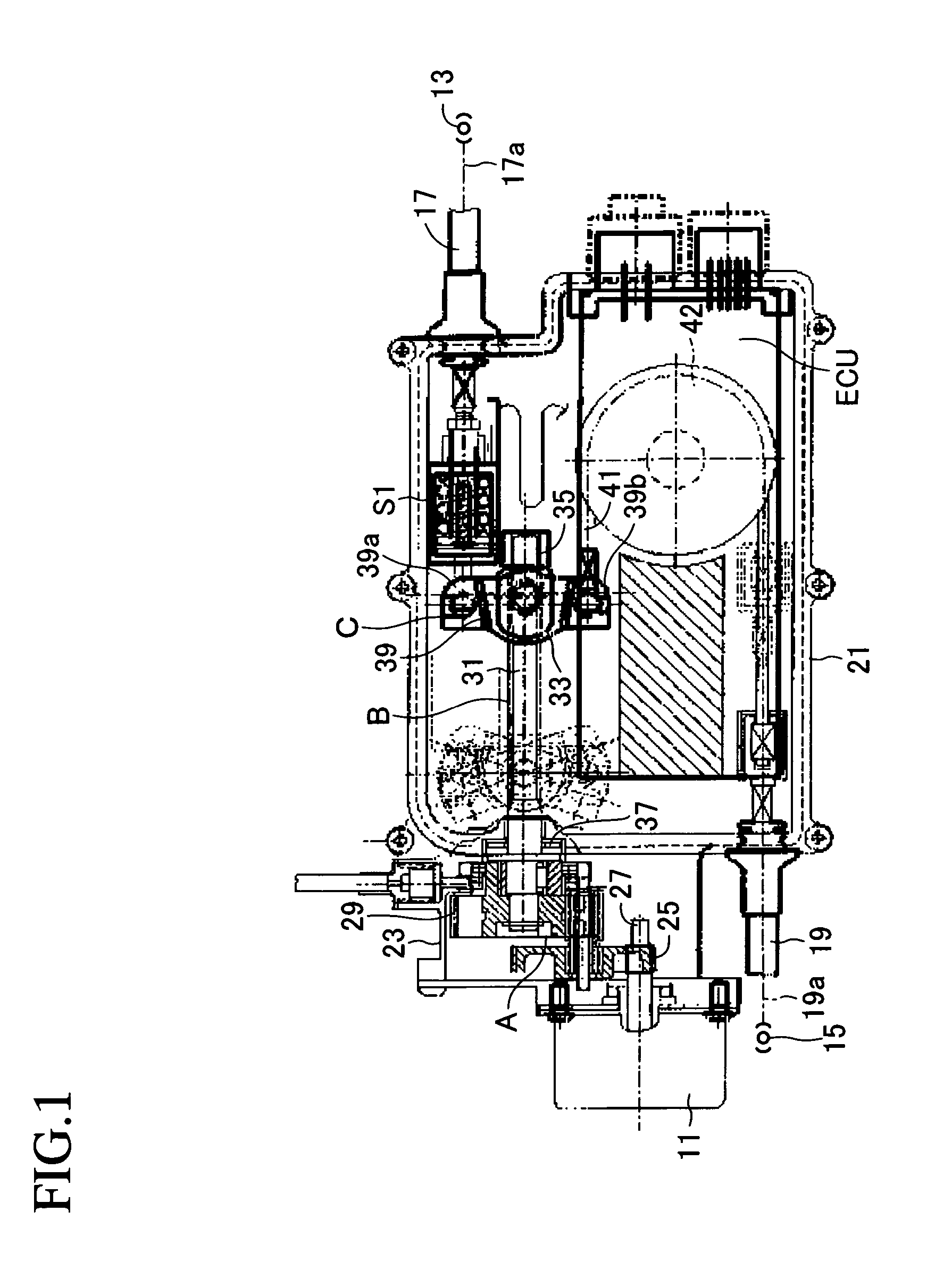
[0027]An embodiment of the present invention will be described with reference to the drawings. FIG. 1 shows an actuator of a motor-driven parking brake apparatus for a vehicle to which the present invention is applied. This actuator comprises a speed reduction mechanism A for transmitting rotational drive force, which is an output of an electric motor 11, while reducing the rotational speed; a conversion mechanism B for converting into a linear drive force the rotational drive force of the electric motor 11 which is transmitted through the speed reduction mechanism A; an equalizer mechanism C driven by the linear drive force output from the conversion mechanism B and distributing the linear drive force to two output portions; two cables 17 and 19 which are connected to the corresponding output portions of the equalizer mechanism C and transmit the linear drive force to corresponding parking brakes 13 and 15; and an electric control unit ECU for controlling the rotation of the electr...


PUM

PropertyMeasurementUnit
output voltageaaaaaaaaaa
forceaaaaaaaaaa
elastic deformationaaaaaaaaaa

Abstract

A force sensor includes a shaft to which a magnet is fixed, and a case which can reciprocate with respect to the shaft and to which a Hall IC element is fixed. The Hall IC element outputs an output voltage which changes in accordance with relative displacement between the Hall IC element and the magnet. A main spring is interposed between the shaft and the case and elastically deforms in accordance with force produced between the shaft and the case in the reciprocating direction. A sub spring is provided in order to impart a preload such that when the amount of elastic deformation of the main spring is substantially zero, no axial clearance is formed between a flange portion of the shaft and one end portion of the main spring, and no axial clearance is formed between the case and the other end of the main spring.

Description

BACKGROUND OF THE INVENTION[0001]1. Field of the Invention[0002]The present invention relates to a force sensor and a motor-driven parking brake apparatus using the force sensor, and is applicable to, for example, a parking brake apparatus for a vehicle.[0003]2. Description of the Related Art[0004]A conventional force sensor includes a first member to which a magnet is fixed; a second member to which an electrical element is fixed, wherein an output voltage of the electrical element varies with relative displacement in relation to the magnet; and a main spring which is interposed between the first member and the second member, and elastically deforms in accordance with force in the reciprocating direction produced between the first member and the second member. International patent application laid-open Nos. 02 / 20324 (WO 02 / 20324 A1) and 02 / 057122 (WO 02 / 057122 A1) disclose such a force sensor.[0005]Also, these publications disclose a motor-driven parking brake apparatus using the a...

Claims


Application Information

Patent Timeline
Patent Type & Authority Patents(United States)
IPC IPC(8): F16D66/00B60L7/00G01B7/16G01L1/00F16D65/28
CPCB60T13/746G01L1/122G01L1/04F16D2125/582
Inventor TACHIIRI, YOSHIKAZUKISO, TAKAHIROSAITO, NOBUYUKI
Owner ADVICS CO LTD
Why Eureka
Try Eureka