Electromagnetic coil for solenoid valve

A technology of solenoid coil and solenoid valve, applied in valve details, valve device, valve operation/release device, etc., can solve the problems of difficult heat dissipation, large magnetic force loss, large electromagnetic force loss, etc.

Inactive Publication Date: 2008-06-11
ZHEJIANG SANHUA CLIMATE & APPLIANCE CONTROLS GRP CO LTD
View PDF0 Cites 7 Cited by
  • Summary
  • Abstract
  • Description
  • Claims
  • Application Information

AI Technical Summary

Problems solved by technology

[0010] However, when the electromagnetic coil of the existing scheme is energized, the magnetic path bottlenecks 17 at its two ends (that is, the two ends of the magnetic sleeve) are the dead ends of the magnetic flux, and the magnetic flux area is small (see Image 6 The magnetic force line c1) shown has large reluctance and large magnetic loss, and requires the working voltage to be within a small fluctuation range (the working voltage range of the existing coil is between 85% and 110% of th

Method used


Image

  • Electromagnetic coil for solenoid valve
  • Electromagnetic coil for solenoid valve
  • Electromagnetic coil for solenoid valve

Examples


Embodiment Construction

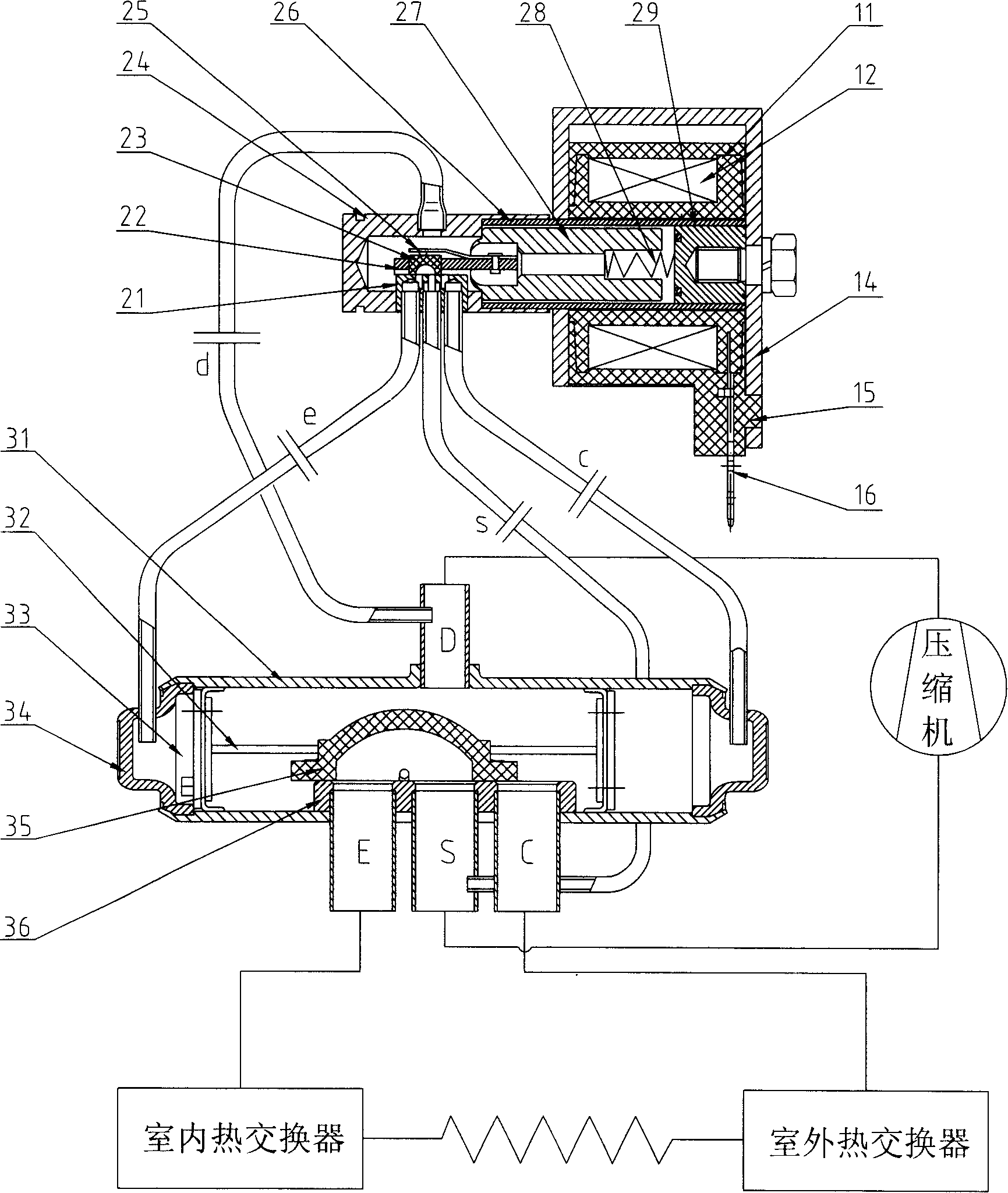
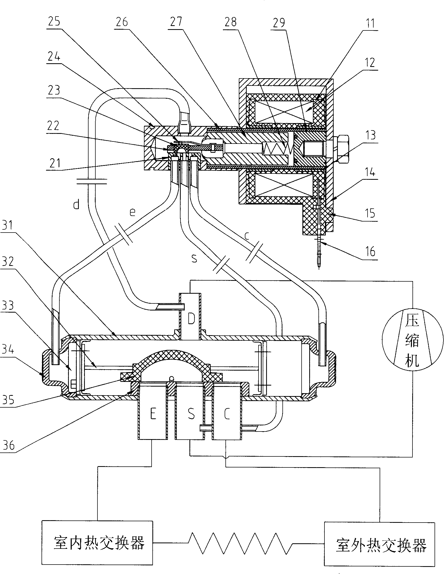
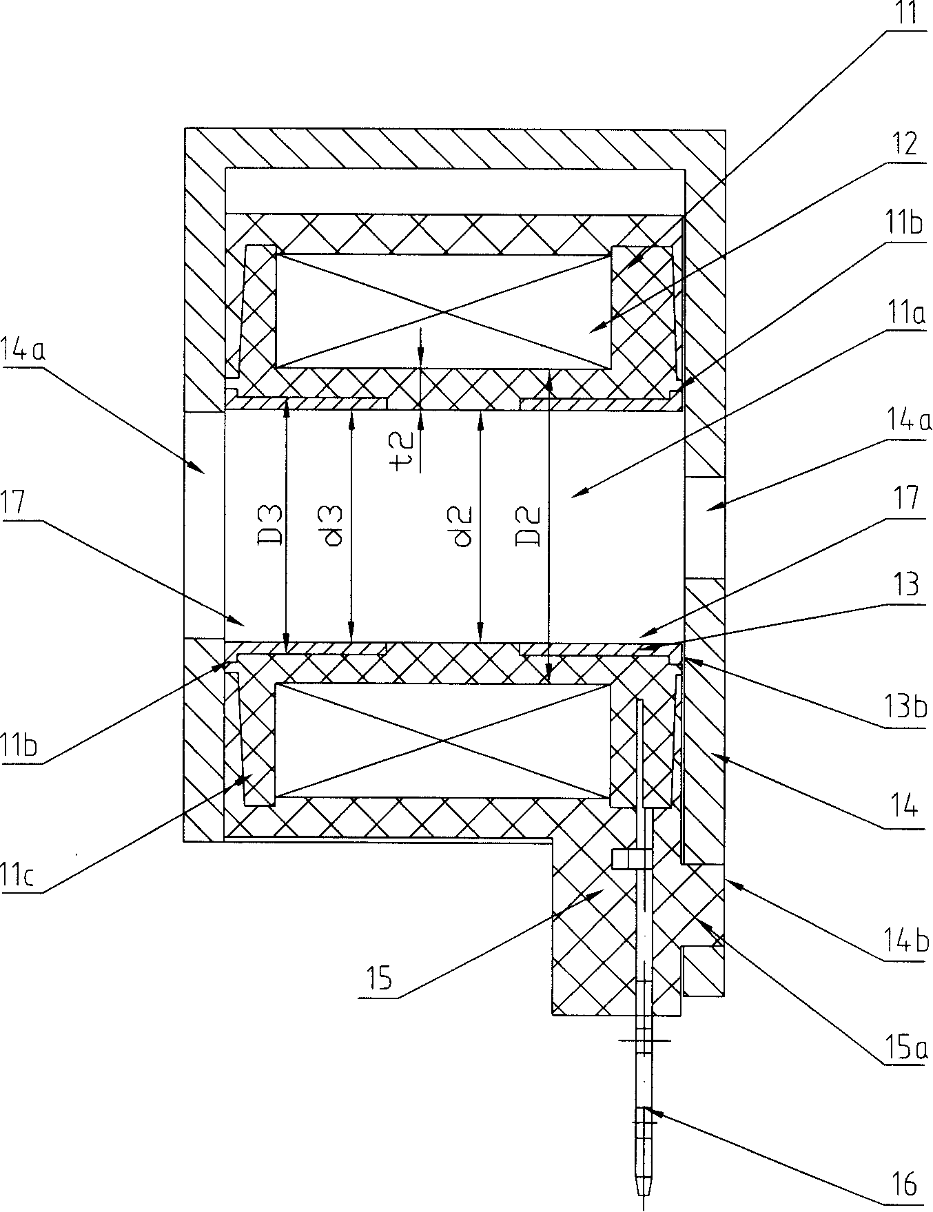
[0031] image 3 The electromagnetic coil shown is mainly composed of a skeleton 11, a winding 12, a magnetically conductive sleeve 13, a magnetically conductive body 14, an insulating coating 15, and a lead wire 16 (or insert), wherein:

[0032] Skeleton 11 is circular tube shape, and its center is inner hole 11a, and the diameter of this inner hole 11a is d2, and the outer diameter of the hole wall of this inner hole 11a is D2, and the thickness of the hole wall of this inner hole 11a is t2, and d2= d1, D2=D1, t2=t1, the two ends of the inner hole 11a have folded edges 11c, so as to form the accommodation part of the wound winding between the folded edges, so as to stabilize the wound winding; The hole 11b expands outward to form a positioning portion 11b;

[0033]The magnetic sleeve 13 is also in the shape of a round tube, made of carbon steel with excellent heat dissipation performance, its inner diameter is d3, the outer diameter is D3, and d3=d2, D1>D3>d2, and one end is...


PUM


Abstract

An electromagnetic coil for electromagnetic valve is provided, which belongs to the electromagnetic control parts. The existing coil has narrow using scope of voltage and large temperature raising volume when being switched on. The invention comprises a winding soil sealed on a framework by an insulated covering and a magnetizer located outside the insulated covering; a down-lead terminal is configured outwards from the winding coil and the framework is attached with internal holes. The invention is characterized in that: a flux sleeve pipe is configured on hole wall of at least one end of the framework internal holes, which shears the same internal diameter with the framework internal holes, so as to form continuous through holes with equal diameter at internal side of the framework and the flux sleeve pipe. When switching on for the coil, the magnetic contour is able to form a loop through the sleeve pipe, which eliminates the ''dead angle'' phenomenon, increases the magnetic flux area at magnetic flux route bottle-neck at two ends of the coil, reduces the magnetic reluctance, lowers the lose of magnetic force, strengthens magnetic field of the overall coil, improves the valve opening performance of the coil, reduces the lose and consumption of magnetic force, thereby deducing the temperature rising of coil and increasing the reliability of valve.

Description

technical field [0001] The invention relates to an electromagnetic coil for an electromagnetic valve used in a heat pump air conditioner, which belongs to electromagnetic control components. Background technique [0002] The structure and function of the electromagnetic coil in the existing electromagnetic valve scheme and figure 1 The electromagnetic four-way reversing valve shown is taken as an example for illustration. The electromagnetic four-way reversing valve is composed of electromagnetic coil, pilot valve and main valve. Its structure and working principle are described as follows: [0003] The main valve includes a cylindrical valve body 31, on which there is a discharge connection D (that is, a high-pressure area) connected to the compressor discharge port, and a suction connection S (that is, a high-pressure area) connected to the compressor suction port. The connecting pipe E connected with the indoor heat exchanger, the connecting pipe C connected with the out...

Claims


Application Information

Patent Timeline
IPC IPC(8): F16K31/06
Inventor 张松飞胡梅宴
Owner ZHEJIANG SANHUA CLIMATE & APPLIANCE CONTROLS GRP CO LTD
Why Eureka
Try Eureka