Permanent magnet generator and wind power generator using the same

A generator and permanent magnet technology, applied in the direction of wind power generators, motors, wind power generation, etc., can solve the problems of low wind power generation efficiency and achieve the effect of increasing the power generation voltage

Inactive Publication Date: 2015-03-04
SHIN ETSU CHEM IND CO LTD
View PDF8 Cites 8 Cited by
  • Summary
  • Abstract
  • Description
  • Claims
  • Application Information

AI Technical Summary

Problems solved by technology

In other words, wind power becomes le

Method used


Image

  • Permanent magnet generator and wind power generator using the same
  • Permanent magnet generator and wind power generator using the same
  • Permanent magnet generator and wind power generator using the same

Examples


Embodiment 1

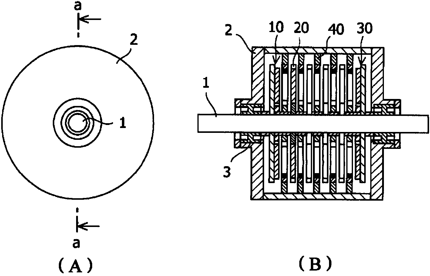
[0074] manufacture figure 1The generator shown in. Manufactured generators are designed with a variable number of stages for the rotor and stator, and the respective power generation voltages produced by changing the number of stages are measured. The shaft is made of stainless steel and has a diameter of 15mm. In the end rotor, eight NdFeB permanent magnets (poles oriented in the axial direction, thickness 4 mm) were concentrically adhered to a ferromagnetic yoke with a diameter of 100 mm and a thickness of 2 mm using an adhesive (epoxy resin), And arrange them in an alternating fashion so that the equidistant poles are oppositely oriented. In addition, in the inner rotor, a stainless steel member with a diameter of 100 mm and a thickness of 4 mm has eight equidistant holes formed for embedding magnets, and the same NdFeB permanent magnet (thickness: 4 mm) is embedded in each hole, and an adhesive (epoxy) fixed. Each rotor is connected to the shaft with a gap of 8 mm (th...

Embodiment 2

[0077] exist Figure 7 In , when the total weight of the magnets is the same, a comparison is made between (A) the three-stage case of two-stage rotor and one-stage stator and (B) the five-stage case of three-stage rotor and two-stage stator (the stator is not shown in the figure). The magnet structures of the rotor and the stator are the same as those of Embodiment 1. Each stator has the same specification. Each rotor has 8 magnetic poles, has a diameter of 100 mm, and has a rotor gap of 8 mm. Furthermore, in the case of the fifth stage, the thickness of the magnet is 4 mm, and in the case of the third stage, the thickness of the magnet is 6 mm. In stage five, the peak voltage is 18V at 450rpm. In level three, the peak voltage is 11V. Therefore, when using the same amount of magnets, the generated voltage can be greatly increased in the five-stage compared with the three-stage.

Embodiment 3

[0079] In another comparison, a three-stage generator having a two-stage rotor and one stator having an increased rotor diameter and an increased number of magnetic poles was compared with the five-stage generator of Embodiment 2. The magnet structures of the rotor and the stator are the same as those of Embodiment 1. The three-stage type generator has a rotor diameter of 130mm and has 10 magnetic poles, and the thickness of its magnets is set at 4.8mm so that the total weight of the magnets is the same as that of the five-stage type. In a three-stage generator, the peak voltage at 450 rpm is 17V. Therefore, although the three-stage type has a 30% larger diameter and a 69% larger surface area than the five-stage type of Example 2, the peak voltage is similar or even lower.


PUM

PropertyMeasurementUnit
Thicknessaaaaaaaaaa
Thicknessaaaaaaaaaa
Thicknessaaaaaaaaaa

Abstract

A power generator is provided which, when used at an electric power generating facility such as a wind power plant, etc., would not be bulky and would not impede wind capture by a wind turbine; instead, it can raise the generated voltage without impeding wind capture. The invention provides a permanent magnet generator comprising a generator shaft; at least three rotors, which are secured with the generator shaft, constituted by a plurality of a plate-shaped structure having a permanent magnet attached thereto, and each disposed in the longitudinal direction of said generator shaft; and a stator, which is plate-shaped structures with a stator coil of a wound copper wire disposed in at least two gaps formed by said rotors, evenly-spaced apart from said generator shaft. The rotors and stators are disposed alternately in the longitudinal direction of said generator shaft, with a total of not less than five stages. Furthermore, a wind power generator obtained by installing a propeller on the shaft of this permanent magnet generator is provided.

Description

[0001] This application is the result of a patent application whose application date is February 29, 2008, and whose invention title is "Permanent Magnet Generator and Wind Power Generator Using It" and whose application number is 200880009137.6 (international application number is PCT / JP2008 / 053673). Divisional application. technical field [0002] The invention relates to a generator, in particular to a generator used as a low-speed generator for wind power, water power and the like. Background technique [0003] During wind power generation, the rotational energy of the blades is transferred to the rotating shaft of the generator so that the rotational energy is converted into electrical energy. The output of the generator is either connected to system power or stored in a battery and used as electricity when necessary. Since the electricity generated depends on the specifications of the generator, the generator needs to be selected to meet the needs of the power generat...

Claims


Application Information

Patent Timeline
IPC IPC(8): H02K16/00H02K21/24
CPCH02K7/1838H02K21/24H02K16/00Y02E10/72F03D9/00H02K7/18
Inventor 美浓轮武久小林秀树宫田浩二
Owner SHIN ETSU CHEM IND CO LTD
Why Eureka
Try Eureka