
Plasma generating device, method of cleaning display panel, and method of manufacturing display panel using the same

a technology of generating device and display panel, which is applied in the manufacture of cold cathode, electric discharge tube/lamp, and electrochemical systems, etc., can solve the problems of deteriorating uniformity of plasma, difficult to manufacture electrodes and dielectrics applicable and affecting the uniformity of plasma, etc., to achieve uniform generation, easy repair and maintenance, and easy to apply to a large area panel

Inactive Publication Date: 2008-04-17
LG ELECTRONICS INC
View PDF5 Cites 5 Cited by
  • Summary
  • Abstract
  • Description
  • Claims
  • Application Information

AI Technical Summary

Benefits of technology

[0011] The present invention is conceived to solve the aforementioned problems in the prior art. Accordingly, it is an object of the present invention to provide a plasma generating device wherein deformation of electrodes is minimized and a gap between dielectrics is kept constant.
[0012] It is another object of the present invention to provide a plasma generating device applicable to a large area panel and easy to maintain.
[0027] According to the plasma generating device of the present invention, there is an advantage in that plasma can be uniformly generated since dielectric plates and electrodes are separately manufactured and assembled. Further, the plasma generating device of the present invention is easily applicable to a large area panel and allows for easy repair and maintenance.

Problems solved by technology

However, the above conventional device has the following problems.
As a result, the uniformity of plasma may be deteriorated.
If the flow rate of reaction gas is changed, the uniformity of plasma is also deteriorated.
Particularly, in a case where the thermal spraying process is employed, it is difficult to manufacture electrode and dielectric applicable to a large area panel.
Furthermore, the conventional device is expensive to manufacture, since the dielectric layer 15 is thermally sprayed on the electrodes 14 and 14′.
Therefore, large exchange costs are necessary and the maintenance is also difficult.

Method used


Image

  • Plasma generating device, method of cleaning display panel, and method of manufacturing display panel using the same
  • Plasma generating device, method of cleaning display panel, and method of manufacturing display panel using the same
  • Plasma generating device, method of cleaning display panel, and method of manufacturing display panel using the same

Examples


Embodiment Construction

[0034] Hereinafter, a plasma generating device according to a preferred embodiment of the present invention will be described in detail with reference to the accompanying drawings.

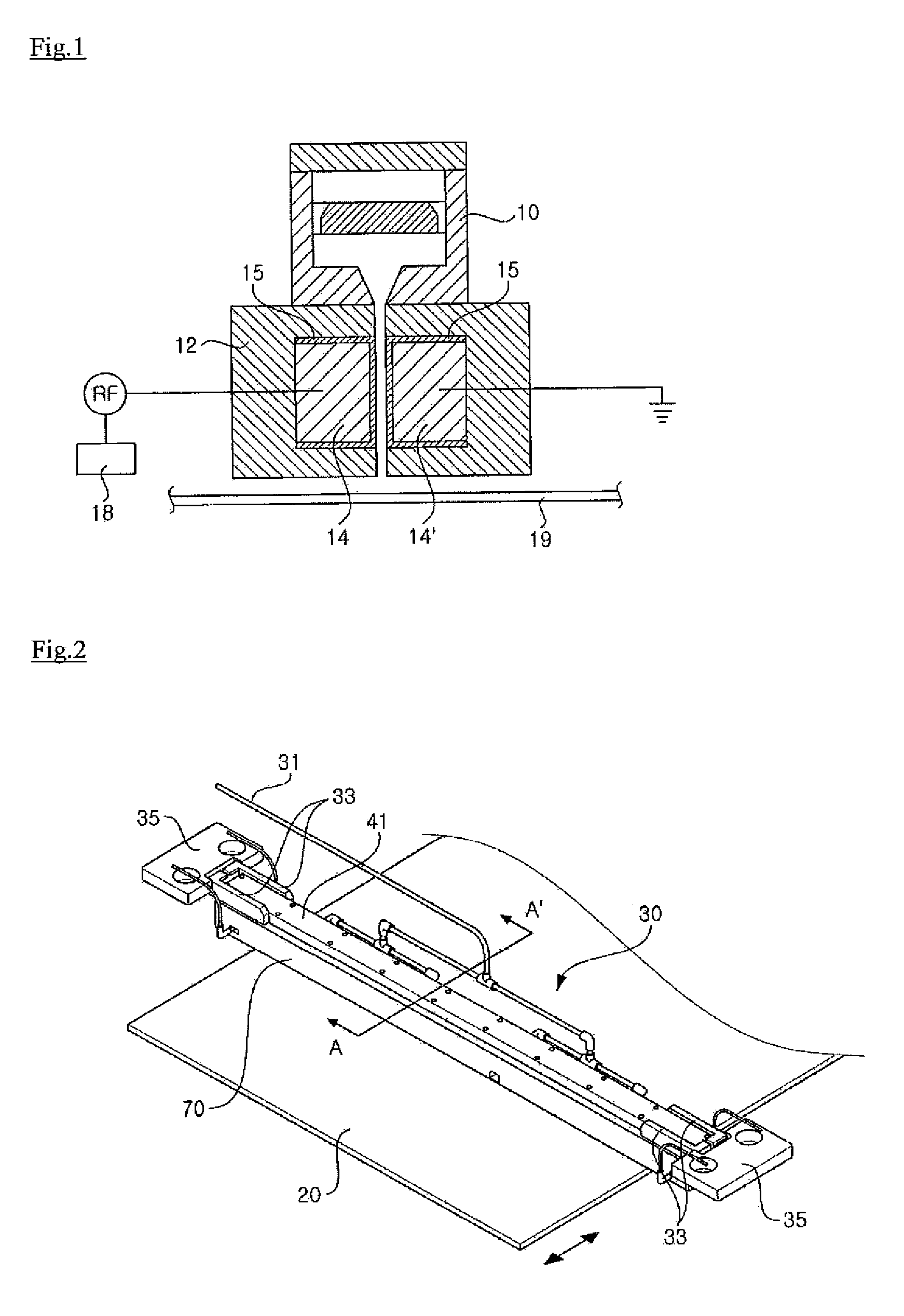
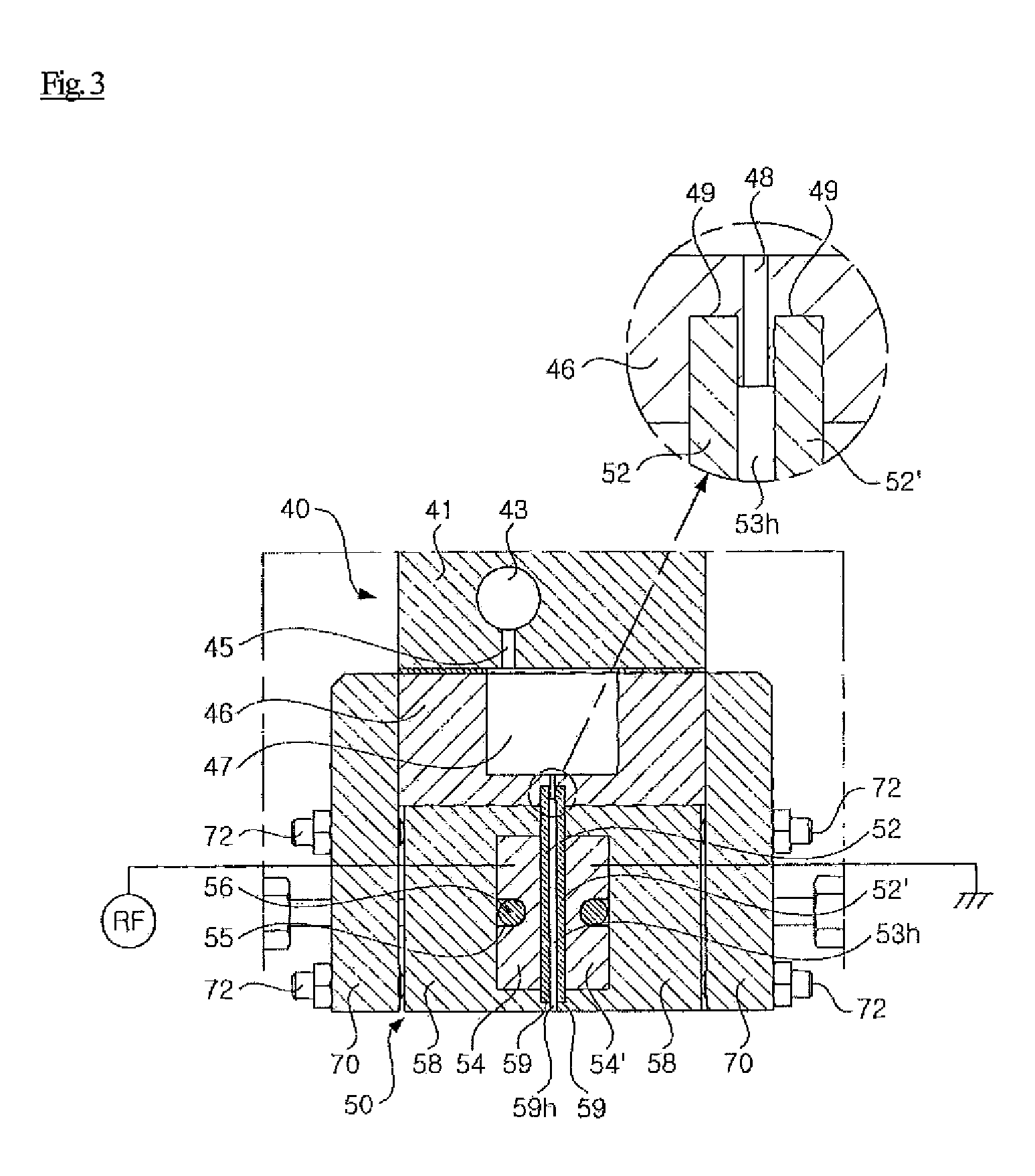
[0035]FIG. 2 is a perspective view of a plasma generating device according to a preferred embodiment of the present invention; FIG. 3 is a sectional view of the plasma generating device according to the present invention, taken along line A-A′ of FIG. 2; FIG. 4 is a longitudinal sectional view of the plasma generating device according to the present invention; and FIG. 5 is a perspective view showing a state where a spacer and an end cover of the plasma generating device according to the present invention are coupled with each other.

[0036] As shown in FIGS. 2 and 3, the plasma generating device of the present invention is provided above an object to be treated, i.e. a panel 20, which is securely placed on a stage (not shown). The plasma generating device includes a nozzle unit 30 formed in a length corre...


PUM


Abstract

The present invention relates to a plasma generating device, a method of cleaning a panel, and a method of manufacturing a display panel using the same. In the present invention, a pair of dielectric plates 52 and 52′ are detachably installed to a nozzle head 50. To this end, an upper end of the dielectric plate 52 or 52′ is inserted into a seating slit 49 formed in a lower portion of a chamber housing 46, and a lower end of the dielectric plate 52 or 52′ is securely placed on and fixed to a stepped portion 59 formed in a lower end of an electrode cover 58. Further, in order to maintain a gap 53h between the dielectric plates 52 and 52′, spacers 64 are inserted in both ends of the gap 53h. According to the present invention so configured, uniform plasma can be generated since the gap between the dielectric plates can be kept constant. Further, the dielectric plates can be easily exchanged and maintained.

Description

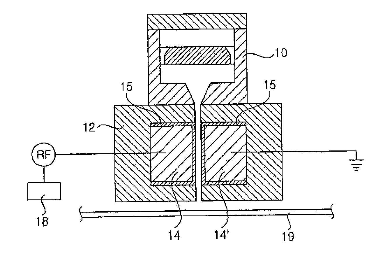
BACKGROUND OF THE INVENTION [0001] 1. Field of the Invention [0002] The present invention relates to a plasma generating device, and more particularly, to a device for performing surface treatment such as deposition, cleaning, ashing and etching on a display panel by applying a radio frequency (REF) power between dielectrics to convert gas flowing between the dielectrics into a plasma state. [0003] 2. Description of the Related Art [0004] Herein, a system for generating plasma under an atmospheric pressure, i.e. a system for generating atmospheric pressure plasma will be mainly explained. [0005]FIG. 1 is schematic view of a conventional atmospheric pressure plasma generating device. As shown in FIG. 1, the plasma generating device includes a gas chamber 10 in which gases are introduced and mixed. A reinforcing cover 12 is installed below the gas chamber 10 to support and protect electrodes 14 and 14′. The electrodes 14 and 14′ include a first electrode 14 and a second electrode 14′ ...

Claims


Application Information

Patent Timeline
IPC IPC(8): H05H1/00H01J9/02
CPCH01J37/32009H01J37/32348H05H1/24H01J37/32724H01J37/32605H05H1/246H01L21/3065
Inventor KIM, TAE-WANYI, CHANG HEON
Owner LG ELECTRONICS INC
Learn More