Solid polymer type fuel battery

a fuel cell and solid polymer technology, applied in the field of polymer electrolyte fuel cells, can solve the problems of reducing the reaction area, affecting the efficiency of electricity generation, so as to achieve the effect of efficiently removing water

Inactive Publication Date: 2006-02-21
MITSUBISHI HEAVY IND LTD
View PDF10 Cites 9 Cited by
  • Summary
  • Abstract
  • Description
  • Claims
  • Application Information

AI Technical Summary

Benefits of technology

[0006]The present invention has been made in view of these circumstances, and an object thereof is to provide a polymer electrolyte fuel cell in which at least a part of each diffusion layer is provided with a gas barrier for preventing the permeation of gas in a direction parallel to the major surface of the diffusion layer, so that the retention of water in the cell can be avoided, uniform electricity generation can be achieved over the whole surface of the cell, and water can be removed efficiently.

Problems solved by technology

However, conventional separators for use in polymer electrolyte fuel cells have a problem in that the fuel gas and the oxidant gas do not flow in conformity with the shape of the groove but bypass it by flowing through the aforesaid diffusion layers, so that water is retained in the cell to cause a corresponding reduction in reaction area, a deterioration in electricity generation performance, and a risk of damage to the cell.
However, this method is advantageous in that the gas pressure losses in the polymer electrolyte fuel cell are increased to cause an increase in power consumption by auxiliary devices such as compressors for feeding the gases, resulting in a reduction in electricity generation efficiency of the whole fuel cell system.

Method used


Image

  • Solid polymer type fuel battery
  • Solid polymer type fuel battery
  • Solid polymer type fuel battery

Examples


first embodiment

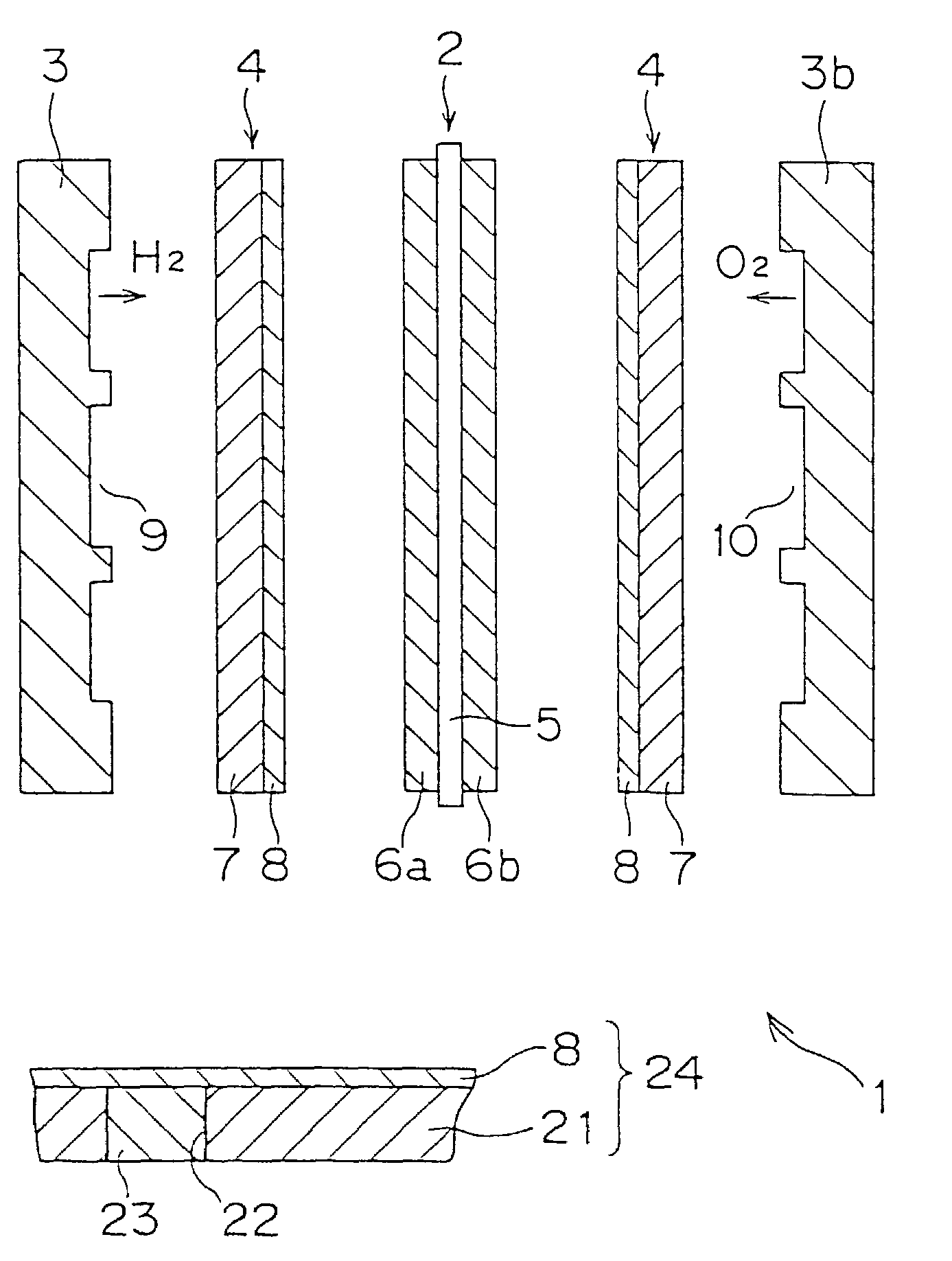
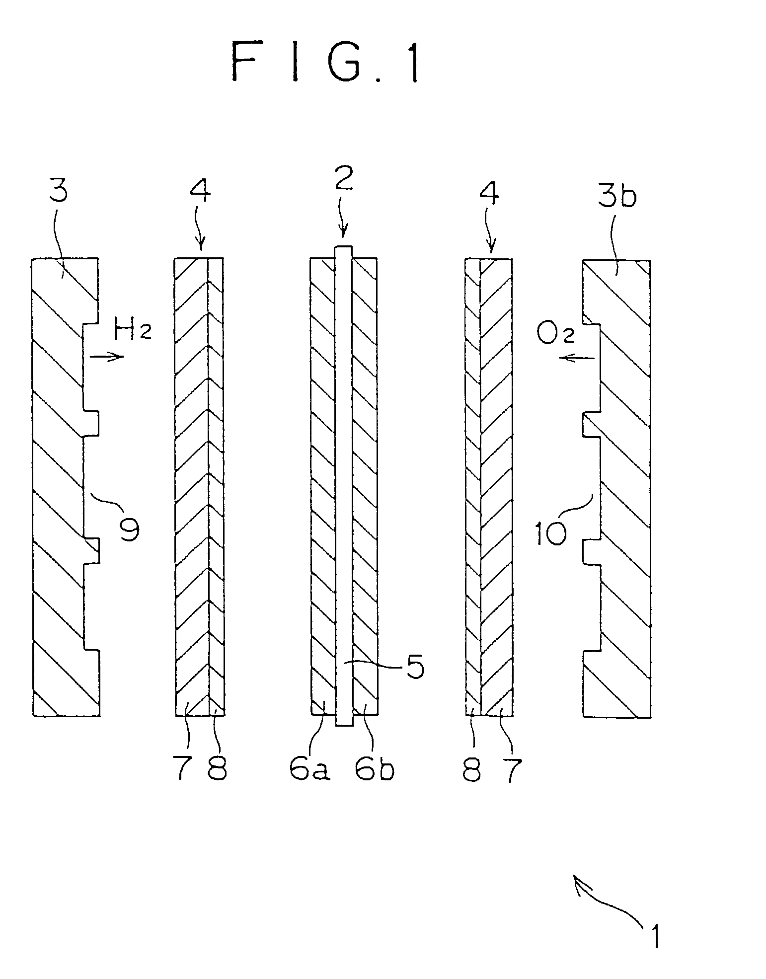
[0029]FIG. 1 is an exploded cross-sectional view illustrating one embodiment of a polymer electrolyte fuel cell in accordance with the present invention. This fuel cell 1 is made up of a cell 2, separators 3a, 3b disposed on both sides of this cell 2 so as to interpose cell 2 therebetween, and diffusion layers 4 disposed between the aforesaid cell 2 and separators 3a, 3b.

[0030]The aforesaid cell 2 consists of a solid polymer film 5 and reaction layers 6a, 6b disposed on both sides of film 5.

[0031]Solid polymer film 5 is a film formed, for example, of a perfluorosulfonic acid.

[0032]Each of the aforesaid diffusion layers 4 consists of carbon paper 7 which is also called a substrate, and a slurry layer 8 formed on one major surface thereof. This carbon paper may be replaced by another electrically conductive porous material such as carbon cloth or nonwoven carbon fabric. Slurry layer 8 may be formed, for example, by mixing hydrophilic carbon black, hydrophobic carbon black and polytet...

second embodiment

[0045]Now, reference is made to FIG. 5. FIG. 5 is a schematic cross-sectional view of a diffusion layer and a separator which constitute a PEFC in accordance with a second embodiment of the present invention. In this embodiment, separator 25 has a projecting part 26 having a greater thickness than its surroundings. Correspondingly to projecting part 26, carbon paper 27 has a compressed layer (gas barrier) 28 formed so as to be recessed as compared with its surroundings. A slurry layer 8 is formed on the aforesaid carbon paper 27 having the aforesaid compressed layer 28.

[0046]Thus, according to the second embodiment, projecting part 26 having a greater thickness than its surroundings is formed at a predetermined position of separator 25, and compressed layer 28 corresponding to this projecting part 27 is formed in carbon paper 27. Consequently, similarly to the first embodiment, the retention of water in the cell can be prevented and uniform electricity generation can be achieved ove...

third embodiment

[0047]Now, reference is made to FIG. 6. FIG. 6 is a schematic cross-sectional view of a diffusion layer constituting a PEFC in accordance with a third embodiment of the present invention. In this embodiment, a gas barrier comprises a resin-impregnated layer 31 formed by infiltrating a resin into the part of carbon paper (substrate) 21 which is intended for the formation of a gas barrier. This resin-impregnated layer 31 has gas tightness and does not allow gas to pass therethrough. A slurry layer 8 is formed on carbon paper 27 having the aforesaid resin-impregnated layer 31.

[0048]Thus, according to the third embodiment, resin-impregnated layer 31 having gas tightness is formed in the part of carbon paper 21 which is intended for the formation of a gas barrier. Consequently, similarly to the first embodiment, the retention of water in the cell can be prevented and uniform electricity generation can be achieved over the whole surface of the cell. Moreover, a uniform gas flow velocity c...


PUM

PropertyMeasurementUnit
porosityaaaaaaaaaa
groove depthaaaaaaaaaa
porosityaaaaaaaaaa

Abstract

A polymer electrolyte fuel cell comprising a cell having a solid polymer film, separators disposed on both sides of the cell so as to interpose the cell therebetween, and diffusion layers disposed between the cell and the separators and each having a substrate comprising an electrically conductive porous material and a slurry layer disposed on the substrate, wherein at least a part of each diffusion layer is provided with a gas barrier for preventing the permeation of gas in a direction parallel to the major surface of the diffusion layer.

Description

TECHNICAL FIELD[0001]This invention relates to improvements in polymer electrolyte fuel cells (PEFCs).BACKGROUND ART[0002]Conventionally, a polymer electrolyte fuel cell is made up of a cell, two separators disposed on both sides of this cell so as to interpose the cell therebetween, and diffusion layers disposed between the aforesaid cell and the separators.[0003]The aforesaid cell consists of a solid polymer film and two reaction layers disposed on both sides of the film. Each of the aforesaid diffusion layers consists of carbon paper and a slurry layer formed on one major surface thereof. A groove for the passage of hydrogen gas is formed in the surface of one separator facing the cell, and a groove for the passage of air is formed in the other separator.[0004]However, conventional separators for use in polymer electrolyte fuel cells have a problem in that the fuel gas and the oxidant gas do not flow in conformity with the shape of the groove but bypass it by flowing through the ...

Claims


Application Information

Patent Timeline
Patent Type & Authority Patents(United States)
IPC IPC(8): H01M2/14H01M4/86
CPCH01M4/8605H01M8/0245H01M8/0241H01M8/0234H01M8/0239Y02E60/50H01M8/1002H01M8/1007H01M4/86H01M8/02
Inventor ITO, HIDEKIKOBAYASHI, TOSHIROMORIGA, TAKUYAYAMADA, AKIHIKO
Owner MITSUBISHI HEAVY IND LTD
Why Eureka
Try Eureka