Light source apparatus, discharge lamp driving method, and projector

a technology of discharge lamp and light source apparatus, which is applied in the direction of energy-saving lighting, instruments, sustainable buildings, etc., can solve the problems of reducing the utilization efficiency of light, increasing the clearance between the electrodes is not desirable, and the clearance between the electrodes becomes wider, so as to achieve stable electrode clearance, stabilize high-quality images, and reduce power consumption

Inactive Publication Date: 2013-01-31
SEIKO EPSON CORP
View PDF2 Cites 6 Cited by
  • Summary
  • Abstract
  • Description
  • Claims
  • Application Information

AI Technical Summary

Benefits of technology

[0036]With the foregoing configuration, the blackening of the discharge lamp can be suppressed and the clearance between the electrodes can be maintained constant while the discharge lamp is driven, irrespective of the luminance of the discharge lamp. Consequently the power consumption can be reduced, and stabilized high-quality images can be displayed.

Problems solved by technology

However, while the discharge lamp is turned on arc discharge takes place between a pair of electrodes, and the electrodes melt because of a high temperature and thus the clearance between the electrodes become wider.
In the case where the discharge lamp is employed for a projector, it is preferable to maintain a narrow clearance between the electrodes so as to illuminate a smaller region, in order to achieve a higher utilization efficiency of the light, and the increase of the clearance between the electrodes is not desirable since it leads to lower utilization efficiency of the light.
The increase of the clearance between the electrodes also incurs fluctuation of the impedance therebetween, and therefore although the discharge lamp provides high efficiency during an initial period of use, impedance mismatch occurs with the lapse of time, which leads to an increase in reactive power and degradation of efficiency.
In this case, however, the discharge lamp main portion is prone to suffer blackening and devitrification, resulting in reduced life span of the discharge lamp.

Method used


Image

  • Light source apparatus, discharge lamp driving method, and projector
  • Light source apparatus, discharge lamp driving method, and projector
  • Light source apparatus, discharge lamp driving method, and projector

Examples


working example

[0132]Specific working examples of the invention will be described here below.

working example 1

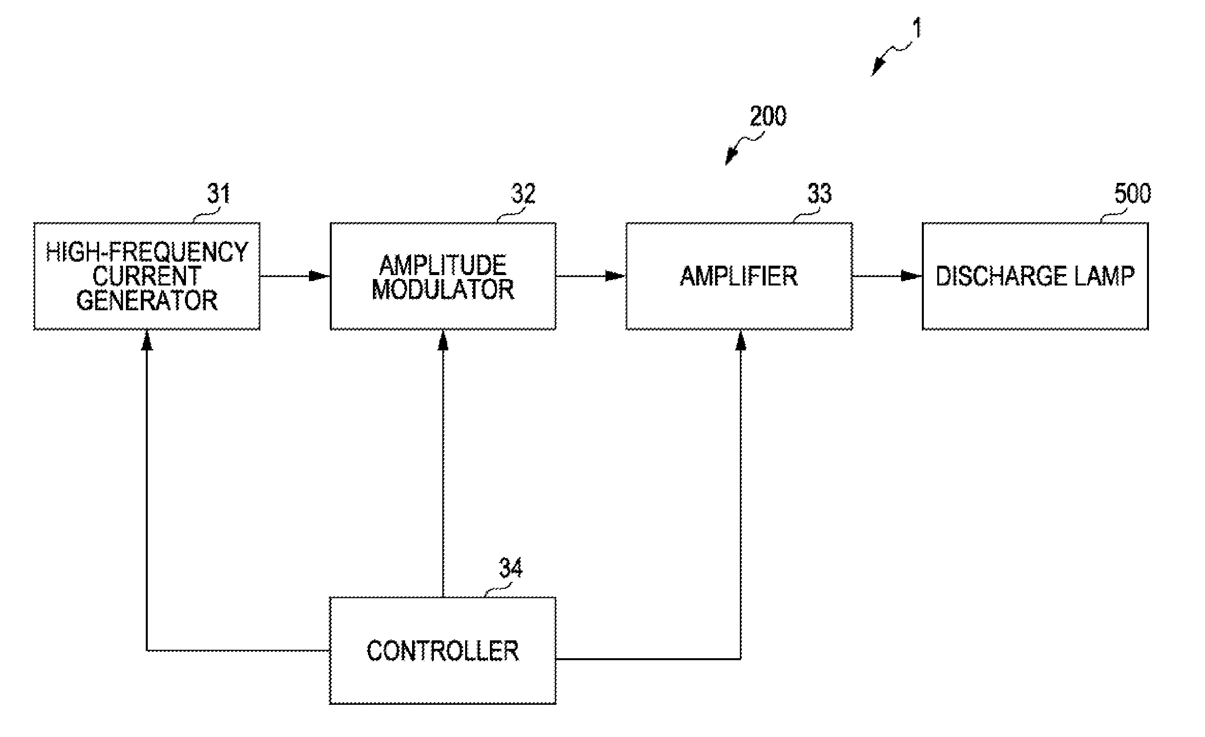
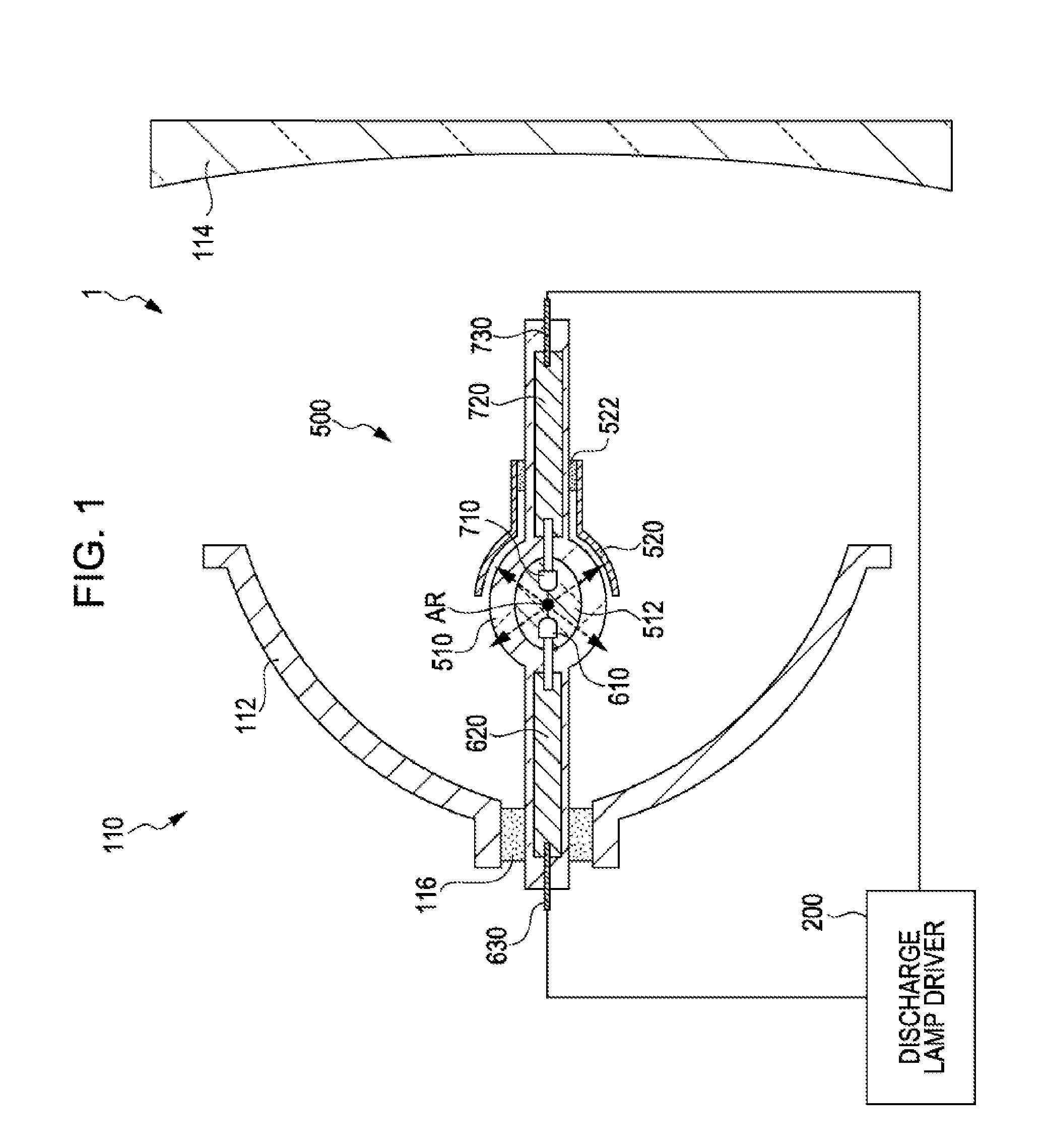
[0133]A light source apparatus as shown in FIG. 1, configured so as to be switched between high luminance and low luminance, was built with the following materials and conditions.

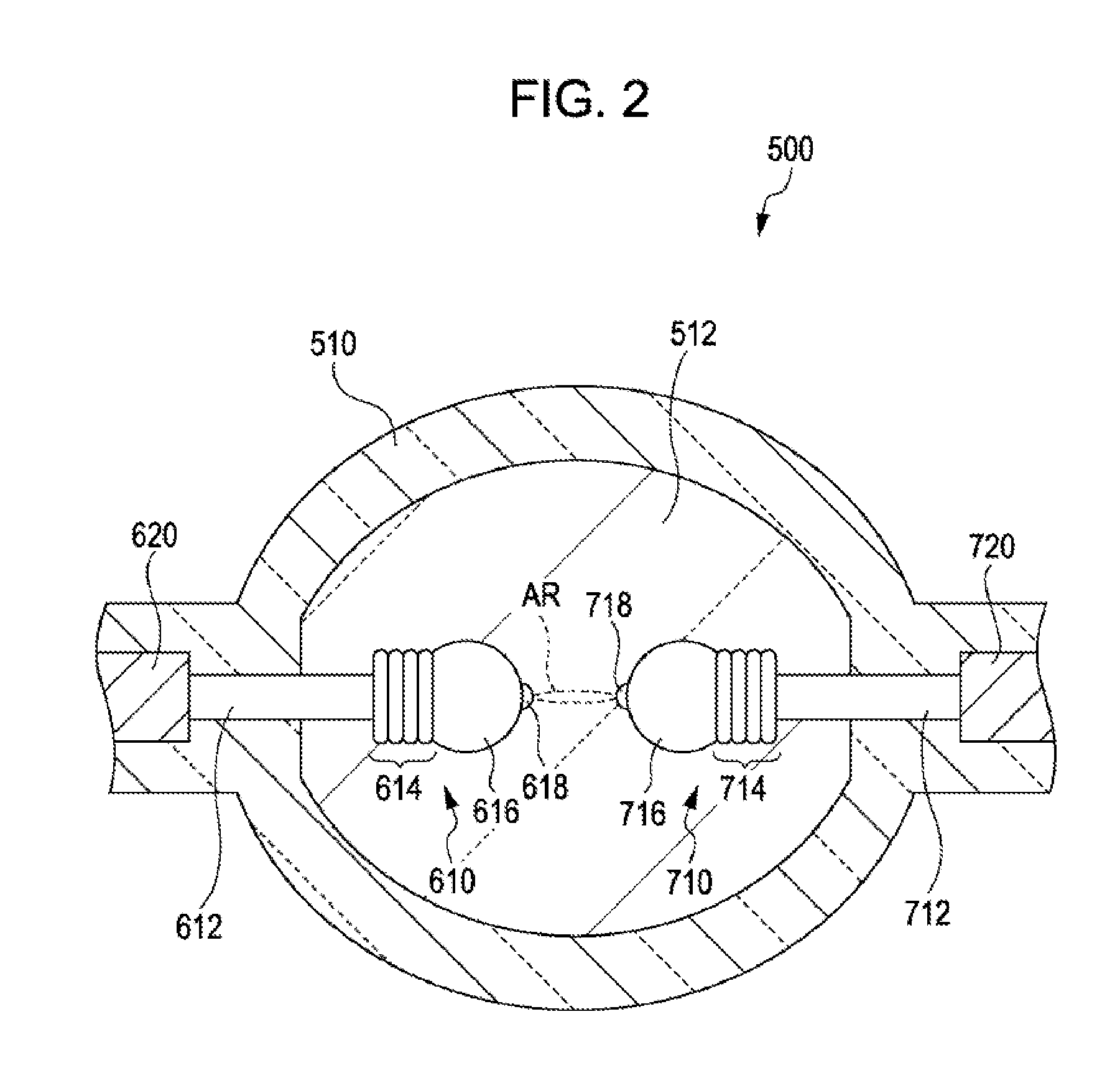
[0134]Material of discharge lamp main portion: Quartz glass

[0135]Enclosure in discharge lamp main portion: Argon, mercury, bromine, methyl bromide

[0136]Working pressure in discharge lamp main portion: 200 atm

[0137]Material of electrodes: Tungsten

[0138]Clearance between electrodes: 1.1 mm

[0139]Rated power of discharge lamp: 200 W

[0140]AC frequency: 5 kHz

[0141]Average driving current for high luminance: 3 A

[0142]Average driving current for low luminance: 2.75 A

[0143]Modulation frequency for high luminance: 300 Hz

[0144]Modulation frequency for low luminance: 300 Hz

[0145]b / a for high luminance: 10%

[0146]b / a for low luminance: 10%

[0147]B / A for high luminance: 50%

[0148]B / A for low luminance: 65%

working example 2

[0149]A light source apparatus generally the same as the working example 1 was built, except for the following differences in conditions.

[0150]Average driving current for high luminance: 3 A

[0151]Average driving current for low luminance: 2.2 A

[0152]Modulation frequency for high luminance: 300 Hz

[0153]Modulation frequency for low luminance: 300 Hz

[0154]b / a for high luminance: 10%

[0155]b / a for low luminance: 10%

[0156]B / A for high luminance: 50%

[0157]B / A for low luminance: 75%


PUM


Abstract

A light source apparatus includes a discharge lamp including a light-emitting container having a cavity in which a discharge medium is enclosed, and a pair of electrodes disposed such that respective tip portions thereof oppose each other in the cavity, and a driving unit that supplies a driving current to the pair of electrodes. The driving current is generated by modulating amplitude of alternating current having a frequency not lower than 1 kHz and not higher than 10 GHz, such that a first section and a second section in which the amplitude is smaller than in the first section are alternately repeated.

Description

BACKGROUND[0001]1. Technical Field[0002]The present invention relates to a light source apparatus, a driving method of a discharge lamp, and a projector.[0003]2. Related Art[0004]Discharge lamps such as a high-pressure mercury lamp and a metal halide lamp are currently employed as a light source of a projector.[0005]Such discharge lamps are driven by supplying, for example, a high-frequency alternating current as the driving current. Such a driving method provides stabilized discharge performance and prevents blackening or devitrification of the discharge lamp main portion thereby suppressing degradation of the life span of the discharge lamp, for example as described in JP-A-2007-115534.[0006]However, while the discharge lamp is turned on arc discharge takes place between a pair of electrodes, and the electrodes melt because of a high temperature and thus the clearance between the electrodes become wider. In the case where the discharge lamp is employed for a projector, it is prefe...

Claims


Application Information

Patent Timeline
Patent Type & Authority Applications(United States)
IPC IPC(8): H05B41/39G03B21/14
CPCH05B41/24H05B41/2885G03B21/2026Y02B20/202Y02B20/208H05B41/2928Y02B20/00
Inventor SUZUKI, JUNICHIKITO, SATOSHI
Owner SEIKO EPSON CORP
Why Eureka
Try Eureka