Managing Pressurized Fluid in a Downhole Tool

Active Publication Date: 2011-05-12
HALLIBURTON ENERGY SERVICES INC
View PDF11 Cites 2 Cited by
  • Summary
  • Abstract
  • Description
  • Claims
  • Application Information

AI Technical Summary

Benefits of technology

[0026]Various embodiments of a perforating sub-assembly including one or more pressure-relief valves according to the present disclosure may include one or more of the following features. For example, the perforating sub-assembly may allow for pressurized fluid (e.g., explosive gases or other pressurized gases, fluids, or combination thereof) generated by discharging one or more perforating guns in the string and captured within the string to be relieved without disassembling all or most of the string at a terranean surface. The perforating sub-assembly may also increase the safety of well site personnel disassembling or partially disassembling the string. The perforating sub-assembly may also allow for easier disassembly of the string by relieving or reducing built up pressure in one or more components caused by the explosive gases. The perforating sub-assembly may also prevent or help prevent an undesirable underbalance condition in the wellbore shortly after discharging one or more perforating guns within the string.
[0027]Various embodiments of a perforating sub-assembly including one or more pressure-relief valves according to the present disclosure may also include one or more of the following features. For example, the perforating sub-assembly may allow for the built up pressure due to explosive gases to be relieved in a controlled manner. The perforating sub-assembly may also allow for the built up pressure to be manually relieved. In some instances, the perforating sub-assembly may allow for the pressure due to explosive gases to be relieved by partially decoupling one or more components within the string. Further, the perforating sub-assembly may allow for a continuous or semi-continuous bleed-off of the pressure as the string is removed from the wellbore to the terranean surface. In some cases, the perforating sub-assembly may bleed off the pressure relative to a wellbore pressure.

Problems solved by technology

Setting off the explosive charge, however, may also trap a portion of explosive gases created by the detonation inside the perforating sub-assembly.
Such explosive gases may be under extremely high pressure, which may need to be relieved when the string reaches the terranean surface.
Relieving the pressure of the explosive gases in the perforating sub-assembly is often difficult if not dangerous.
For example, wellsite personnel charged with releasing such pressure often do not know the extent of the pressure built up in the perforating sub-assembly.
Further, if the pressure is in excess of maximum design limits of the perforating gun, damage to the perforating sub-assembly and / or injury to such personnel may occur as attempts to relieve the pressure ensue.

Method used


Image

  • Managing Pressurized Fluid in a Downhole Tool
  • Managing Pressurized Fluid in a Downhole Tool
  • Managing Pressurized Fluid in a Downhole Tool

Examples


Embodiment Construction

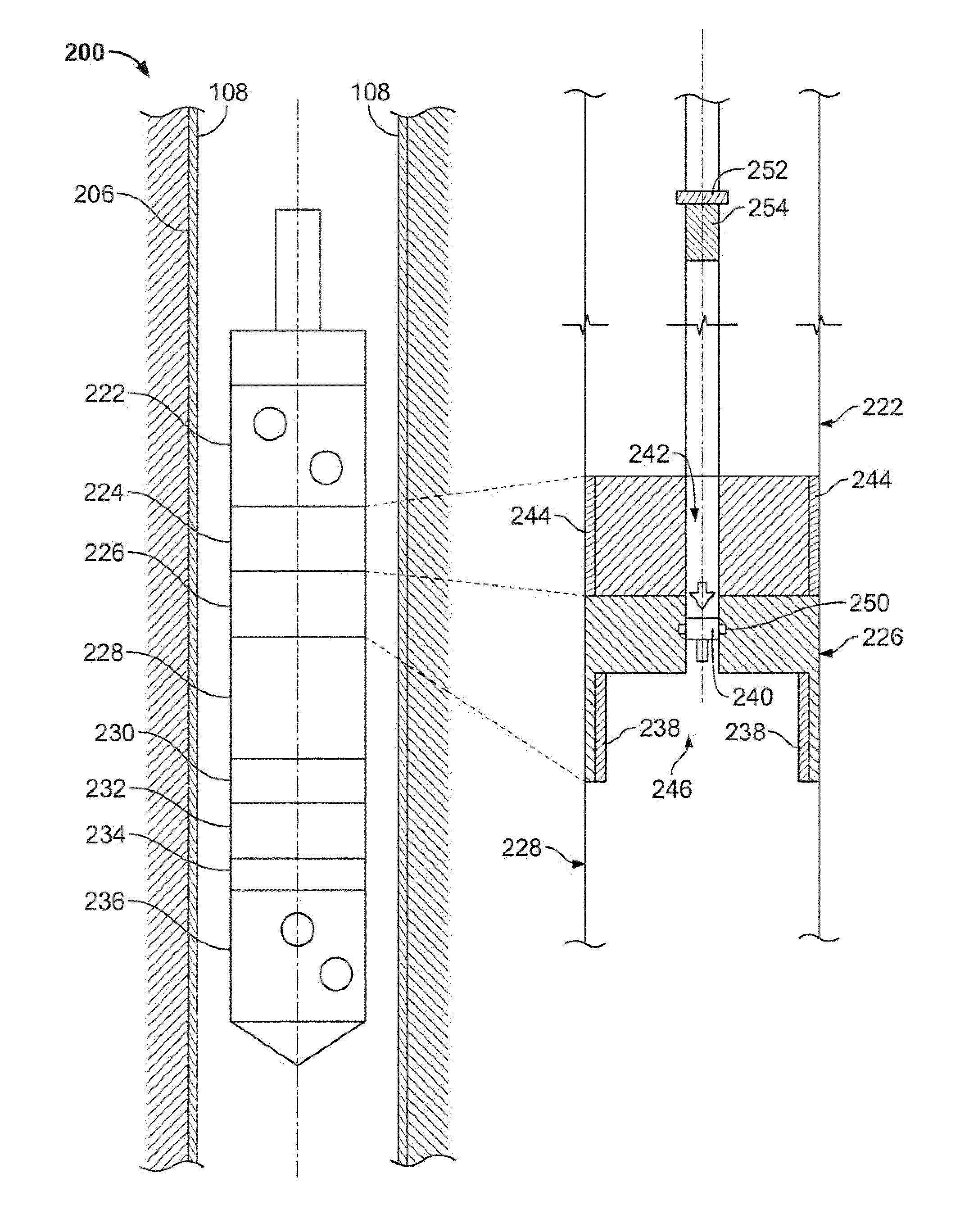
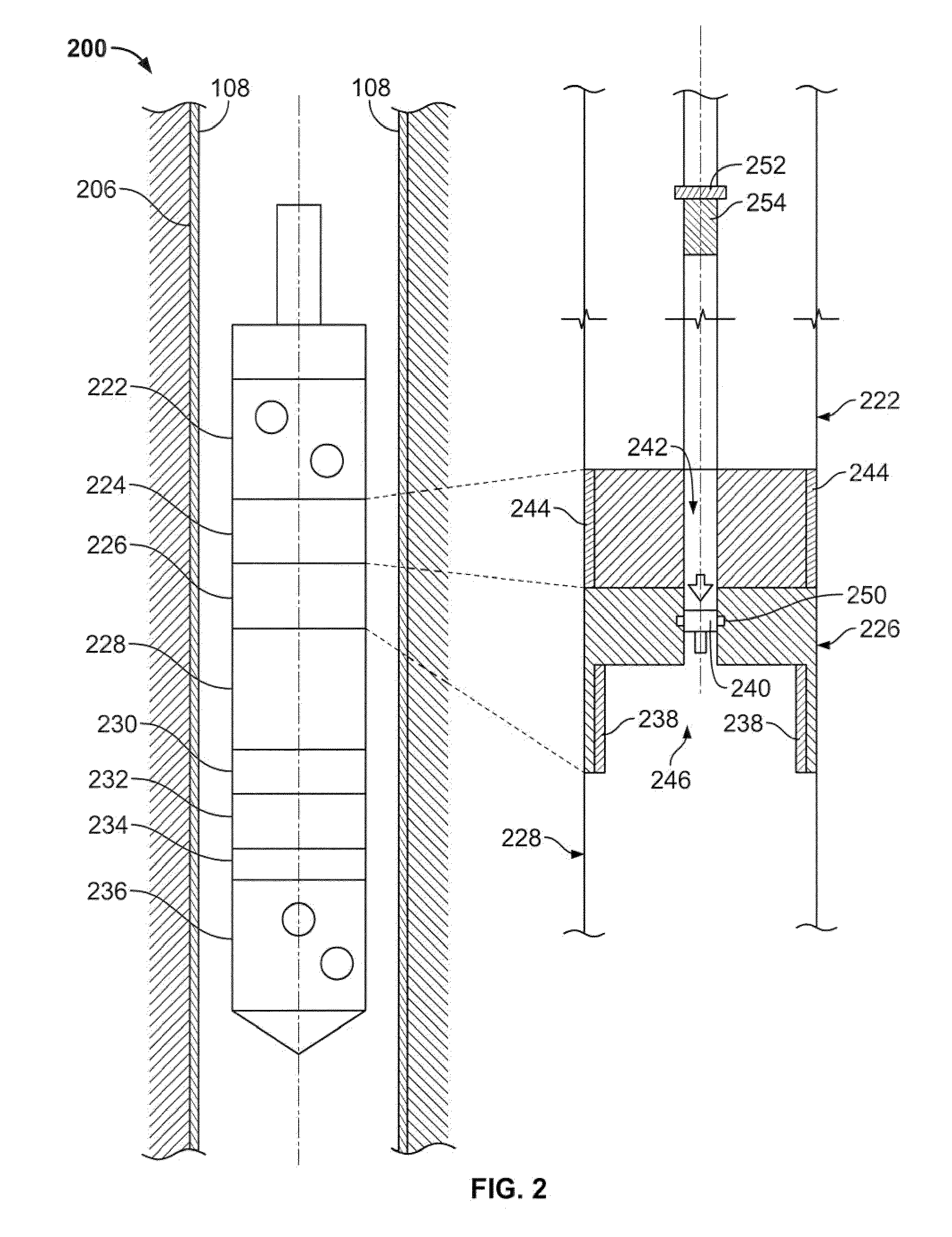
[0009]In one general embodiment, a wellbore apparatus includes a connector sub assembly having a body, the body having a first end adapted to couple to a first perforating sub component and a second, axially opposed end adapted to couple to a second perforating sub component. The connector sub body defines a cavity proximate the second end of the connector sub body; and a flow path in fluid communication with the cavity and a location exterior to the wellbore apparatus. The apparatus includes a valve residing in the flow path and actuatable to block or allow fluid flow from the cavity, through the flow path, to the location exterior to the wellbore apparatus.

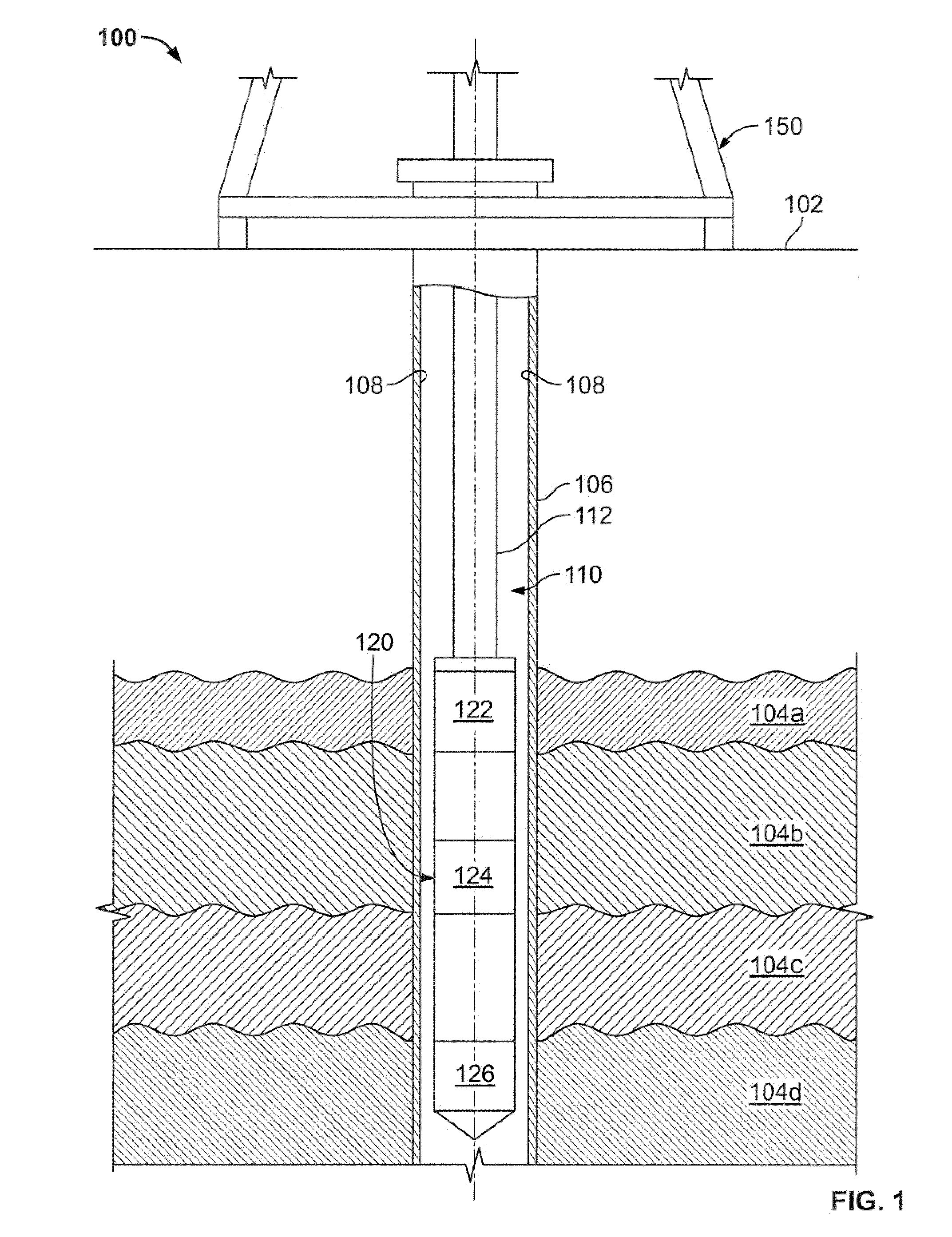
[0010]In another general embodiment, a method for relieving a pressurized fluid from a downhole tool includes withdrawing at least a portion of a downhole tool through a wellbore, the downhole tool including a connector sub assembly having a body. The body has a first end adapted to couple to a first perforating sub component an...


PUM


Abstract

A wellbore apparatus includes a connector sub assembly having a body, the body having a first end adapted to couple to a first perforating sub component and a second, axially opposed end adapted to couple to a second perforating sub component. The connector sub body defines a cavity proximate the second end of the connector sub body; and a flow path in fluid communication with the cavity and a location exterior to the wellbore apparatus. The apparatus includes a valve residing in the flow path and actuatable to block or allow fluid flow from the cavity, through the flow path, to the location exterior to the wellbore apparatus.

Description

TECHNICAL BACKGROUND[0001]This disclosure relates to managing pressurized fluid from discharging one or more perforating devices in a wellbore.BACKGROUND[0002]Explosive devices are often used to create holes (i.e., perforations) in a wall of a wellbore so as to allow one or more hydrocarbon fluids to enter the wellbore from a subterranean zone. These devices, typically called perforating guns, contain one or more explosive charges designed to perforate the wall of the wellbore, including a casing and / or cement, so as to produce such fluids. Modern perforating guns may typically consist of a string of explosive devices connected by such other components as isolation subs, tandems, and box to pin connectors, to name but a few. In some instances, the string of perforating guns may be over 1000 feet long. Such strings allow for perforating the wellbore at multiple subterranean zones, each of which may produce one or more hydrocarbon fluids (e.g., oil, gas).[0003]In some instances, space...

Claims


Application Information

Patent Timeline
IPC IPC(8): E21B43/11E21B34/00E21B29/02
CPCE21B43/1195
Inventor HALES, JOHN H.BURLESON, JOHN D.
Owner HALLIBURTON ENERGY SERVICES INC
Why Eureka
Try Eureka