Structured illumination probe and method

a structured illumination and probe technology, applied in the field of surgical instruments and methods, can solve the problems of difficult to achieve desirable contrast in a practical surgical setting, unsuitable for micro-surgery inside the eye, and unknown illuminator probes that can efficiently provide structured illumination safe for use in ophthalmic procedures

Active Publication Date: 2011-05-12
ALCON INC
View PDF16 Cites 32 Cited by
  • Summary
  • Abstract
  • Description
  • Claims
  • Application Information

AI Technical Summary

Benefits of technology

[0010]Another embodiment of the present invention is a structured illumination probe, which can be a small-gauge illumination probe, comprising: an optical fiber, operable to receive a light beam and transmit the light beam to illuminate an area; a handpiece, operably coupled to the optical fiber; an optical element, a proximal end of the optical element optically coupled to a distal end of the optical fiber, for receiving the light beam and scattering the light beam to illuminate an area, wherein the surface area of the proximal end of the optical element is greater than the surface area of the distal end of the optical fiber; and a cannula, operably coupled to the handpiece, for housing and directing the optical fiber and the optical element The area can be a surgical site, such as the retina.
[0011]Other embodiments of the present invention can include a method for structured illumination of a surgical field using a structured illuminator in accordance with the teachings of this invention, and a surgical handpiece embodiment of the structured illuminator of

Problems solved by technology

Because endoscopic illumination is provided by inserting a probe tip through a small incision, the fact that the probe may have to be articulated through the incision point, and that the illumination probe is at a finite angel of incidence relative to a viewing microscope, providing desirable contrast is difficult to realize in a practical

Method used


Image

  • Structured illumination probe and method
  • Structured illumination probe and method
  • Structured illumination probe and method

Examples


Embodiment Construction

[0027]Preferred embodiments of the present invention are illustrated in the FIGURES, like numerals being used to refer to like and corresponding parts of the various drawings.

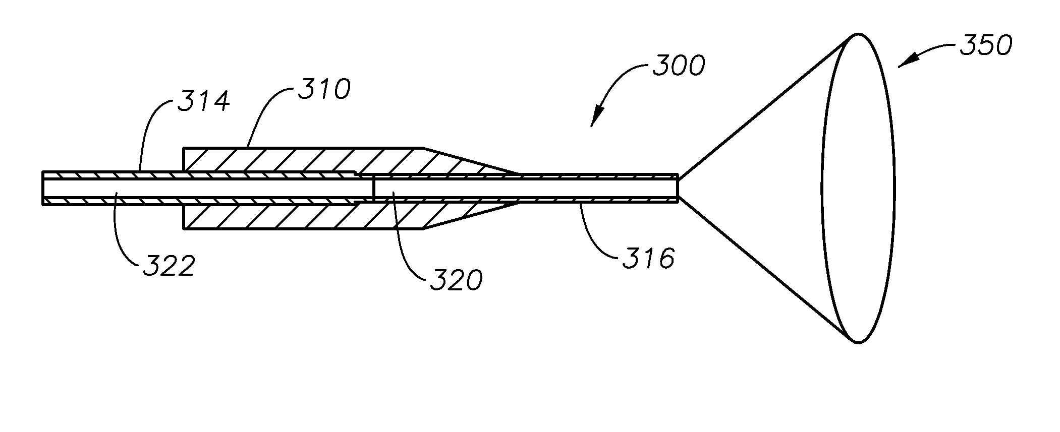
[0028]The various embodiments of the present invention provide for a small gauge (e.g., 19, 20, 25 or smaller gauge) optical fiber based endo-illuminator device for use in surgical procedures, such as in vitreo-retinal / posterior segment surgery. Embodiments of this invention can comprise a handpiece, such as the Alcon-Grieshaber Revolution-DSP™ handpiece sold by Alcon Laboratories, Inc., Fort Worth, Tex., connected to a small gauge cannula (e.g., 19, 20, 25 or smaller gauge). The inner dimension of the cannula can house an optical fiber, which can terminate in an optical coupling to an optical element, such as a light guide, or in a selectable light guide and distal optical fiber combination, in accordance with the teachings of this invention. Embodiments of the structured illuminator can be configured for use ...


PUM


Abstract

A structured illumination probe is disclosed, one embodiment comprising: an optical fiber, to receive and transmit a light beam; a handpiece, coupled to the optical fiber; an optical element, comprising a distal optical fiber and a distal light guide, wherein the proximal ends of the distal optical fiber and the distal light guide can be selectably optically coupled to the optical fiber, for receiving the light beam and scattering the light beam to illuminate an area, and wherein the surface area of the proximal end of the distal light guide is greater than the surface area of the distal end of the optical fiber; an actuator, coupled to the handpiece, for selectably coupling the optical fiber to the distal optical fiber and the distal light guide; and a cannula, coupled to the handpiece, for housing and directing the optical fiber and the optical element.

Description

TECHNICAL FIELD OF THE INVENTION[0001]This application claims priority to U.S. Provisional Patent Application Ser. No. 61 / 260,143 filed on Nov. 11, 2009.[0002]The present invention relates generally to surgical instrumentation and methods. In particular, the present invention relates to surgical systems and methods for illuminating an area during eye surgery. Even more particularly, the present invention relates to an illumination probe for providing structured illumination of a surgical field.BACKGROUND OF THE INVENTION[0003]In ophthalmic surgery, and in particular in vitreo-retinal surgery, surgeons rely on a variety of techniques to provide contrast in order to visualize features of interest on the retina. Techniques that are commonly used are brightfield imaging, darkfield imaging, and gradient field imaging. Gradient field imaging is created by illuminating a feature by partially overlapping an illumination spot so that parts of the feature are well lit by direct illumination a...

Claims


Application Information

Patent Timeline
IPC IPC(8): A61B1/06
CPCA61B3/12A61B19/5202A61F9/007A61B2019/5206A61B2017/00469A61B90/30A61B2090/306
Inventor PAPAC, MICHAEL J.SMITH, RONALD T.
Owner ALCON INC
Why Eureka
Try Eureka