Wireless multiconductor cable test system and method

Inactive Publication Date: 2004-04-08
THE UNITED STATES OF AMERICA AS REPRESENTED BY THE SECRETARY OF THE NAVY
View PDF12 Cites 41 Cited by
  • Summary
  • Abstract
  • Description
  • Claims
  • Application Information

AI Technical Summary

Benefits of technology

0021] Accordingly, the present invention provides a tester for testing multiconductor cable wherein the multiconductor cable may be comprised of a plurality of separate conductors. The tester may comprise one or more elements such as, for instance, a first cable tester unit connectable to a first end of the multiconductor cable. The first cable tester unit is preferably operable for producing one or more test signals individually on each of the plurality of separate conductors. A second cable tester unit is connectable to the second end of the multiconductor cable, which may be several hundred feet away. The second cable tester unit is operable for individually monitoring each of the plurality of separate conductors to detect the one or more test signals produced by the first cable tester unit. In preferred embodiment, a first wireless transceiver is provided for the first cable tester that is operable for wirelessly transmitting control signals for testing of the multiconductor cable. A second wireless transceiver is provided for the second cable tester operable for wirelessly transmitting test result data for the plurality of separate conductors to the first wireless transceiver. A display may be provided for displaying test results received by the first wireless transceiver from the second wireless transceiver which shows the condition of the multiconductor cable. In a preferred embodiment, individual AC power supply connections separately power the first and second cable tester units. The units may comprise a hardwired serial connection between the first cable tester unit and the second cable tester unit to provide an alternatively useable data link between the first cable tester unit and the second cable tester unit. In another embodiment, the hardwired serial connection may be provided instead of the wireless transceivers. The first and second cable tester units each preferably utilize a controller, such as a microprocess

Problems solved by technology

Many types of problems may arise with such cables including but not limited to, miswirings such as miswiring of appropriate pins on the plugs of opposite ends of the cable, open circuits or lack of continuity, shorts, and the like.
Such temporary extender cables tend to be heavy.
Storage, maintenance, relocation, set up, and the like, of these extender cables for testing purposes tends to be cumbersome, time consuming, and costly.
The extender cables are prone to damage when they are temporarily installed, removed, and reinstalled as a system installation progresses.
The extender cables are usually laid out in general passageways where they are subject to abuse from foot tra

Method used


Image

  • Wireless multiconductor cable test system and method
  • Wireless multiconductor cable test system and method

Examples


Embodiment Construction

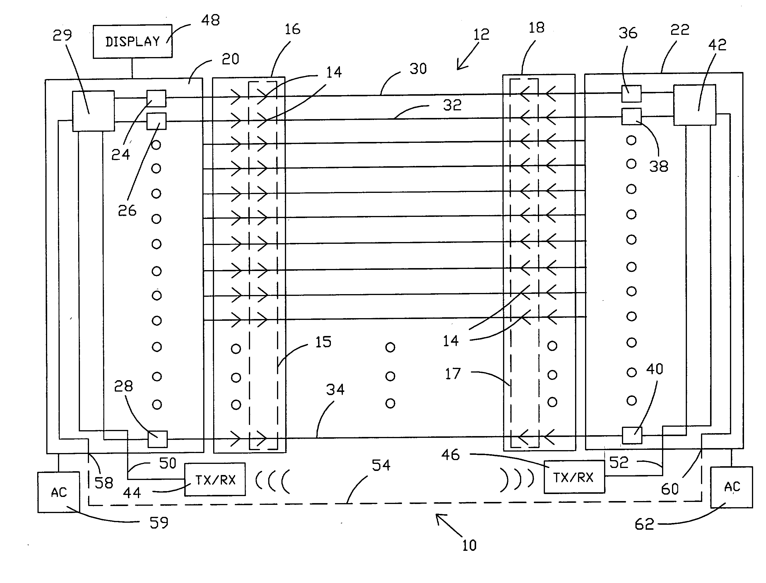
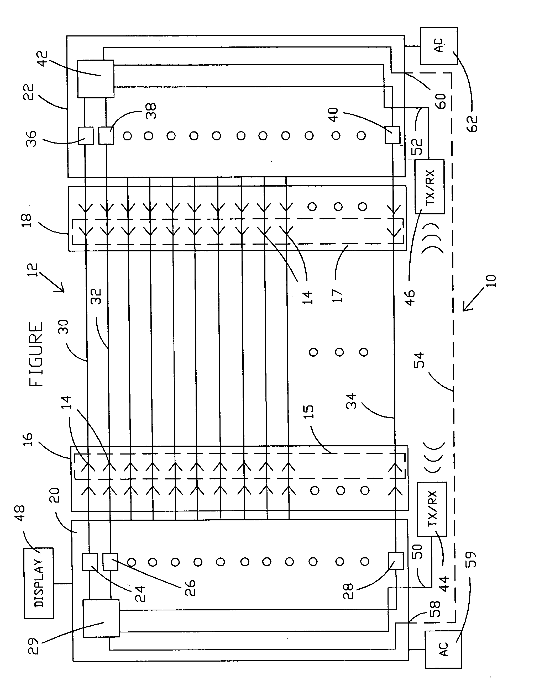
[0024] Referring now to the drawing and, more particularly to the FIGURE, there is shown wireless multiconductor cable test system 10 in accord with one possible embodiment of the present invention. Wireless multiconductor cable test system 10 may be utilized to provide the benefits of closed loop testing of multiconductor cable 12 without the need for bulky and time consuming usage of multiconductor extender cables. A typical multiconductor cable 12 will have one hundred pin / plug contacts 14 at each end of multiconductor cable 12. More generally, a multiconductor cables will have at least five to nine or more separate conductors and / or twisted wire pairs, but will typically have many more separate conductors. However, the present invention can be used for testing multiconductor cables having any number N of conductors. Pin / plug contacts 14, which may be of different types, are normally mounted in respective cable end plugs 15 and 17 at opposite ends of multiconductor cable 12. Plug...


PUM


Abstract

A tester for testing multiconductor cable having a first tester is connectable to a first end of the multiconductor cable. The first tester produces one or more test signals individually on each conductor of the cable. A second tester is connectable to the second end of the cable at a remote location. The second tester monitors each of the plurality of separate conductors to detect the test signals produced by the first tester. Preferably, a first wireless transceiver is provided for the first tester that wirelessly transmits control signals to automatically coordinate testing procedure control. A second wireless transceiver joined to the second tester wirelessly transmits test result data.

Description

STATEMENT OF THE GOVERNMENT INTEREST[0001] The invention described herein may be manufactured and used by or for the Government of the United States of America for Governmental purposes without the payment of any royalties thereon or therefore.[0002] (1) Field of the Invention[0003] The present invention relates generally to systems and methods for testing multi-conductor cables and, more particularly, to a wireless multiconductor cable tester and method.[0004] (2) Description of the Prior Art[0005] Multiconductor cable is required for many electronic devices such as digital equipment to provide a plurality of signal paths for digital signals. A typical multiconductor cable may be comprised of many conductors to permit simultaneous parallel transmission of multiple digital signals, control signals, DC power levels, and the like. For instance, one typical multiconductor cable has a standard one hundred conductor construction with suitable connectors on either end. Depending on the ty...

Claims


Application Information

Patent Timeline
IPC IPC(8): G01R31/02
CPCG01R31/023G01R31/021G01R31/58G01R31/60
Inventor PEREIRA, FERNANDO J.HUOT, RAYMOND U.
Owner THE UNITED STATES OF AMERICA AS REPRESENTED BY THE SECRETARY OF THE NAVY
Why Eureka
Try Eureka