
Portable active fluid powered ankle-foot orthosis

a technology of active fluid and ankle-foot orthosis, applied in the field of orthosis, can solve problems such as affecting the quality of life, weakened or impaired muscles, and clearance problems

Inactive Publication Date: 2011-05-12
THE BOARD OF TRUSTEES OF THE UNIV OF ILLINOIS
View PDF12 Cites 54 Cited by
  • Summary
  • Abstract
  • Description
  • Claims
  • Application Information

AI Technical Summary

Benefits of technology

[0013]Embodiments of the present invention provide, among other things, a portable active pneumatically-powered ankle foot orthosis. An example device comprises a lower leg mount and a foot bed pivotally coupled to the lower leg mount at or proximate to an ankle position. A pneumatically powered rotary ac...

Problems solved by technology

Pathology or injury that affects the ankle joint can significantly impact quality of life by impairing some or all functional aspects of gait.
Both dorsiflexor and plantarflexor muscle groups of the ankle-foot complex are critical to normal walking, and undesirable compensatory gait patterns result from weakened or impaired muscles of either type.
Weak dorsiflexors affect both stance and swing phases of gait, causing clearance issues during swing phase and uncontrolled deceleration of the foot at initial stance.
Swing is affected because the foot does not effectively clear the ground due to weak or absent dorsiflexor muscles, which results in a steppage-type gait pattern that is commonly called foot drop.
This lack of control results in an often audible foot slap that impacts stance initialization.
Weak plantarflexors primarily affect stance phase by reducing stability and propulsive power of the individual, particularly during limb support.
Passive devices generally limit the foot angle to the neutral position (i.e., 90° between leg and foot), which can produce an unnatural gait but prevents further damage or injury and provides limited mobility to people that use them.
Passive orthoses do not provide direct assistance during the propulsive phase of gait.
This type of AFO has limited robustness and does not adapt to changing walking conditions.
Semi-active devices can store energy, such as in a spring, and provide braking assistance but do not add energy into the system to aid propulsion.
Such devices cannot be used outside the clinic or laboratory.
Typical active and semi-active devices use large electromechanical actuators that are cumbersome and unattractive.
Common passive devices inhibit motion at undesirable times. Common and more newly developed semi-active devices can also stop or resist motion at undesirable points and only store energy provided by a user, which may not be ideal for treating many gait impairments.

Method used


Image

  • Portable active fluid powered ankle-foot orthosis
  • Portable active fluid powered ankle-foot orthosis
  • Portable active fluid powered ankle-foot orthosis

Examples


Embodiment Construction

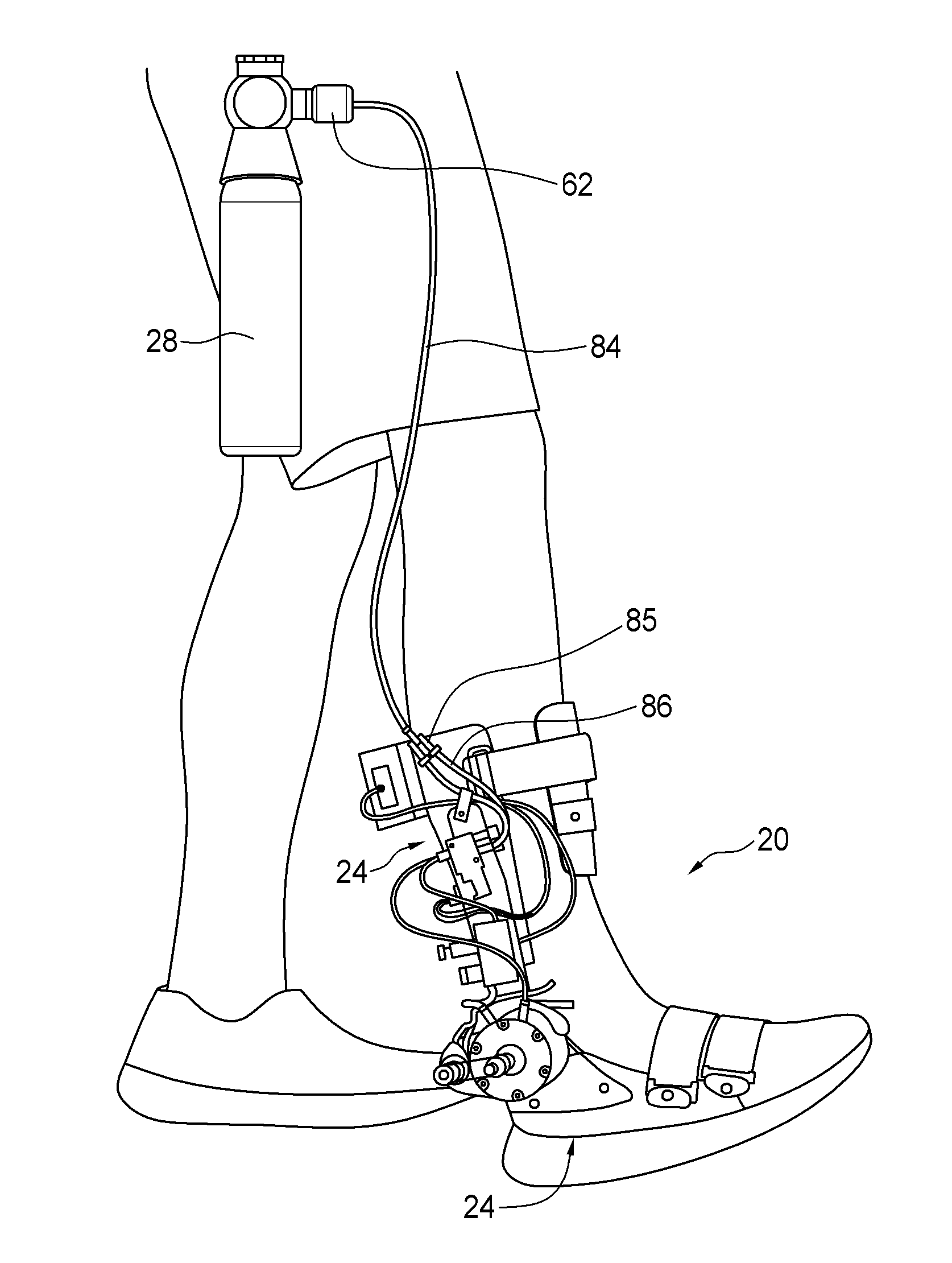
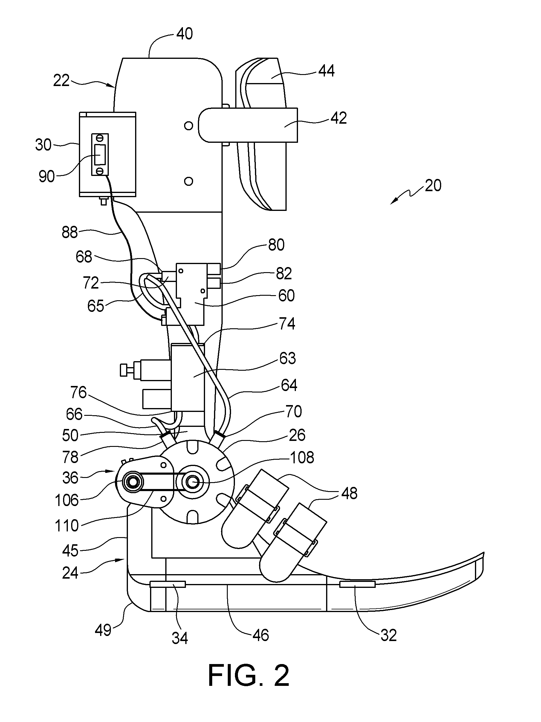
[0028]Embodiments of the invention provide a portable active pneumatically powered ankle foot orthosis. Example devices of the invention are pneumatically powered by a self-contained and portable (e.g., wearable) fluid power source, such as a container (e.g., bottle, cylinder, cartridge, etc.) of CO2 or other suitable fluid. CO2 containers that may be used include, as nonlimiting examples, containers used in the power tool industry. The CO2 or other fluid container can be worn on a belt or another area of the body. The fluid power source is coupled to a rotary actuator at or proximate to the ankle joint that is controlled by an on-board controller, e.g., a microcontroller having a microprocessor and memory. The torque generated by the actuator can be used for both motion control of the foot and to provide supplemental torque for the individual during gait.

[0029]A compact and lightweight structure attaches to the lower leg of a user, for instance around the leg, to provide a lower le...


PUM


Abstract

A portable active pneumatically-powered ankle foot orthosis. A lower leg mount and a foot bed are pivotally coupled at or proximate to an ankle position. A pneumatically powered rotary actuator is configured to receive power from a wearable fluid power source and provide controlled force and resistance to aid or inhibit relative rotation of the foot bed and the lower leg mount. Embedded sensors provide feedback from the device.

Description

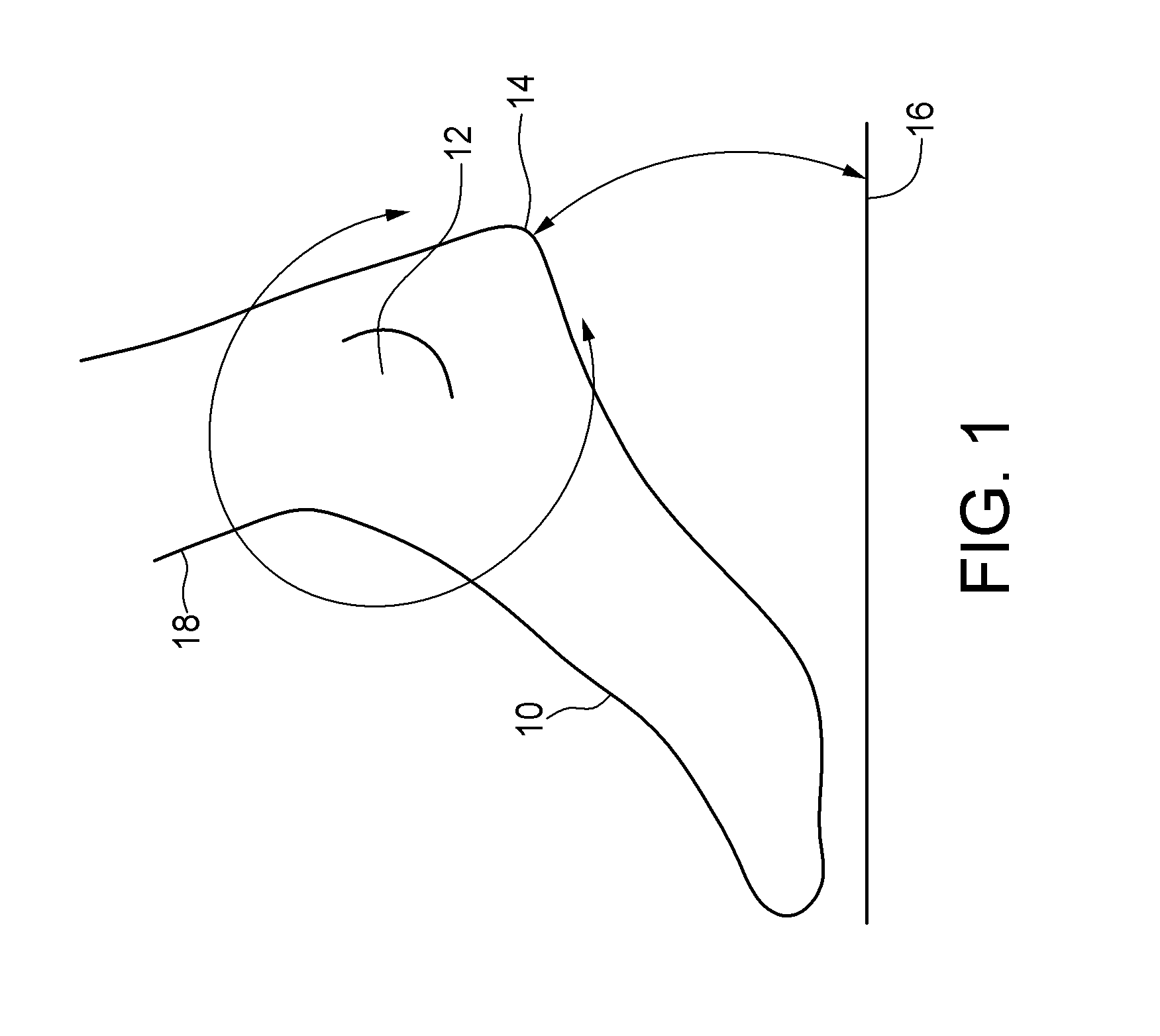
PRIORITY CLAIM AND REFERENCE TO RELATED APPLICATION[0001]This application claims the benefit of U.S. Provisional Application Ser. No. 61 / 248,674, filed Oct. 5, 2009, under 35 U.S.C. §119.STATEMENT OF GOVERNMENT INTEREST[0002]This invention was made with Government support under Contract No. 0540834 awarded by the National Science Foundation. The Government has certain rights in the invention.FIELD OF THE INVENTION[0003]A field of the invention is orthotics.BACKGROUND OF THE INVENTION[0004]During normal gait, the ankle joint, shank, and foot play important roles in all aspects of locomotion, including shock absorption, stance stability, energy conservation and propulsion. For example, FIG. 1 shows foot 10 and ankle joint 12 movement during part of normal gait. A gait cycle is typically defined from the initial contact of the heel 14 to the following heel contact. At the initiation of the gait cycle, impact forces are dissipated when energy is absorbed by the soft tissues at the heel ...

Claims


Application Information

Patent Timeline
IPC IPC(8): A61H1/02
CPCA61H1/0266A61H3/008A61H2201/165A61H2201/5041A61H2201/5061A61H2201/1676A61H2201/5071A61H3/00A61H2201/1238A61H2201/1642A61H2201/5069
Inventor HSIAO-WECKSLER, ELIZABETH T.GILMER, JOEL NELSONKOGLER, GEZALOTH, ERICSHORTER, K. ALEXTHOMAS, JASON EVAN
Owner THE BOARD OF TRUSTEES OF THE UNIV OF ILLINOIS
Learn More