
System and Method For Visualizing Data Corresponding To Physical Objects

a technology of physical objects and visualizing systems, applied in the direction of instruments, directional drilling, borehole/well accessories, etc., can solve problems such as misleading data distortion, affecting the magnitude of data, and affecting the accuracy of data visualization,

Inactive Publication Date: 2011-05-12
WILSON BRIAN D +3
View PDF13 Cites 18 Cited by
  • Summary
  • Abstract
  • Description
  • Claims
  • Application Information

AI Technical Summary

Problems solved by technology

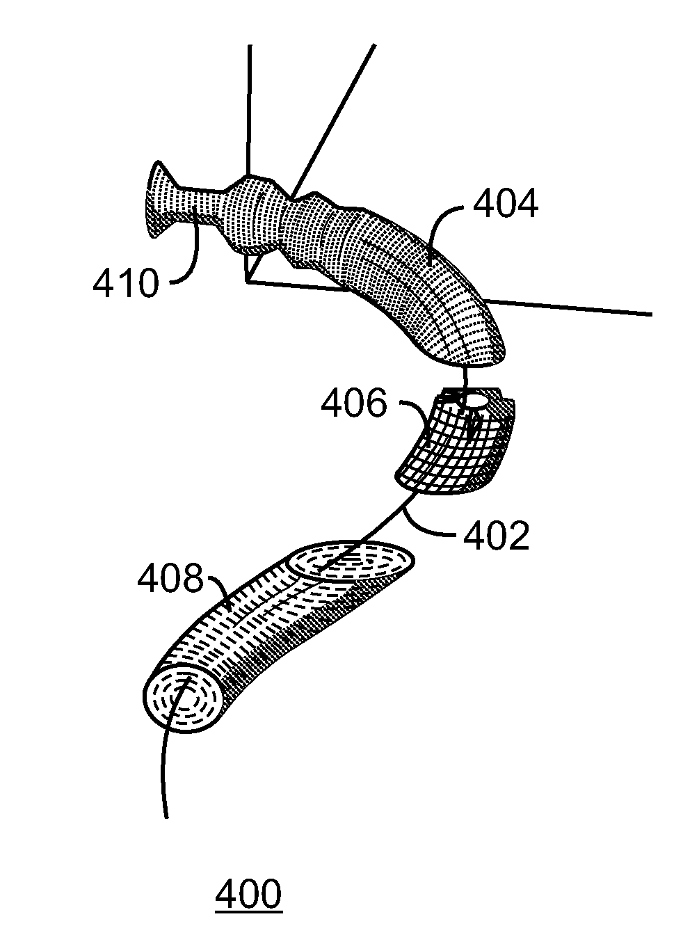
Determining an accurate representation of a well path in the subsurface, however, presents a complex problem.
Another related problem involves the positioning of data near an estimated well path in a way that reduces distortion of the data.
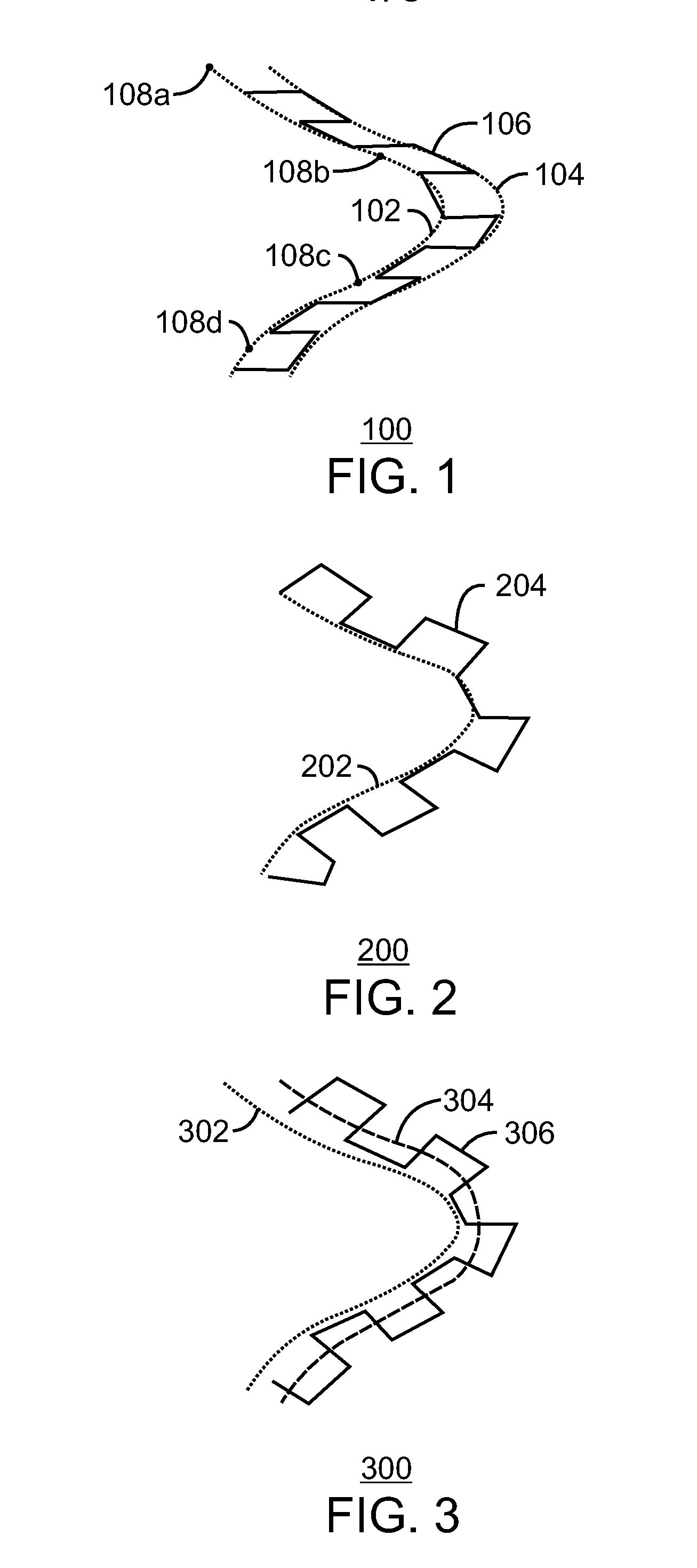
Displaying this data in a three-dimensional scene along a well path can lead to misleading distortions of this data, since well paths are generally displayed as line segments rather than the more realistic curved path.
However, problems rendering log data in two-dimensional space may occur when the data is graphed along the curved well path.
Limitations in the rendering space can result in misleading spacing of data points or distortions in the magnitude of the data.

Method used


Image

  • System and Method For Visualizing Data Corresponding To Physical Objects
  • System and Method For Visualizing Data Corresponding To Physical Objects
  • System and Method For Visualizing Data Corresponding To Physical Objects

Examples


Embodiment Construction

In the following detailed description section, specific embodiments are described in connection with preferred embodiments. However, to the extent that the following description is specific to a particular embodiment or a particular use, this is intended to be for exemplary purposes only and simply provides a description of the exemplary embodiments. Accordingly, the present techniques are not limited to embodiments described herein, but rather, it includes all alternatives, modifications, and equivalents falling within the spirit and scope of the appended claims.

At the outset, and for ease of reference, certain terms used in this application and their meanings as used in this context are set forth. To the extent a term used herein is not defined below, it should be given the broadest definition persons in the pertinent art have given that term as reflected in at least one printed publication or issued patent.

As used herein, the term “3D data volume” refers to a collection of data t...


PUM


Abstract

There is provided a system and method for providing a visualization of data corresponding to a physical structure, the data relating to a property that varies along a curved path. An exemplary method comprises defining the curved path by successively computing values for a position, a measured depth and an exit vector for a plurality of path points along the curved path. The exemplary method also comprises providing a visual representation corresponding to the data for the property.

Description

FIELDThe present techniques relate to providing visualizations of data corresponding to physical objects and analysis thereof In particular, an exemplary embodiment of the present techniques relates to determining a curved path that corresponds to a physical object and simultaneously providing visualizations of data corresponding to multiple user-selected properties of interest along the curved path, such as a well bore.BACKGROUNDThis section is intended to introduce various aspects of the art, which may be associated with embodiments of the disclosed techniques. This discussion is believed to assist in providing a framework to facilitate a better understanding of particular aspects of the disclosed techniques. Accordingly, it should be understood that this section is to be read in this light, and not necessarily as admissions of prior art.Many fields of study involve the analysis of data corresponding to properties of interest at various locations within physical structures. Exampl...

Claims


Application Information

Patent Timeline
Patent Type & Authority Applications(United States)
IPC IPC(8): G06F17/50E21B43/00
CPCE21B7/04
Inventor WILSON, BRIAN D.DATTA, INDRACHENG, YAO-CHOUCHARTRAND, TIMOTHY A.
Owner WILSON BRIAN D
Learn More