Scan conditioning setting apparatus, medical apparatus and method of setting scan condition

Inactive Publication Date: 2011-05-12
GE MEDICAL SYST GLOBAL TECH CO LLC
View PDF17 Cites 20 Cited by
  • Summary
  • Abstract
  • Description
  • Claims
  • Application Information

AI Technical Summary

Benefits of technology

[0008]The scan condition setting apparatus according to the first aspect of the invention stores scan conditions corresponding to respective combinations of scan times and image quality therein. Accordingly, an operator si

Problems solved by technology

As the number of scan conditions to be set increases, a burden on the operator also becomes large.
However, in general, it is not easy to understand the degree of change of the ima

Method used


Image

  • Scan conditioning setting apparatus, medical apparatus and method of setting scan condition
  • Scan conditioning setting apparatus, medical apparatus and method of setting scan condition
  • Scan conditioning setting apparatus, medical apparatus and method of setting scan condition

Examples


Example

[0025]FIG. 1 is a schematic diagram showing a magnetic resonance imaging apparatus according to a first embodiment of the invention.

[0026]The magnetic resonance imaging apparatus (hereinafter referred to as MRI (Magnetic Resonance Imaging) apparatus) 1 has a magnetic field generator 2, a table 3, a reception coil 4, etc.

[0027]The magnetic field generator 2 has a bore 21 in which a subject 13 is accommodated, a superconductive coil 22, a gradient coil 23 and a transmission coil 24. The superconductive coil 22 applies a static magnetic field B0 and the gradient coil 23 applies a gradient pulse. The transmission coil 24 transmits an RF pulse.

[0028]The table 3 has a cradle 31 for conveying the subject 13. The subject 13 is conveyed to the bore 21 by the cradle 31.

[0029]The reception coil 4 is attached to a head region 13a of the subject 13 and receives each magnetic resonance signal from the head region 13a.

[0030]The MRI apparatus 1 further has a sequencer 5, a transmitter 6, a gradien...

Example

(2) Second Embodiment

[0076]Although the slider bar 124 is configured so as to be capable of selecting the combination of the scan time and the image in the first embodiment, a slider bar 124 employed in a second embodiment is configured so as to be capable of selecting the width of a field of view therein. The slider bar 124 employed in the second embodiment will be explained below. Incidentally, a hardware configuration according to the second embodiment is identical to that of the first embodiment.

[0077]FIG. 14 is a diagram showing one example of a display screen for displaying the slider bar 124 employed in the second embodiment.

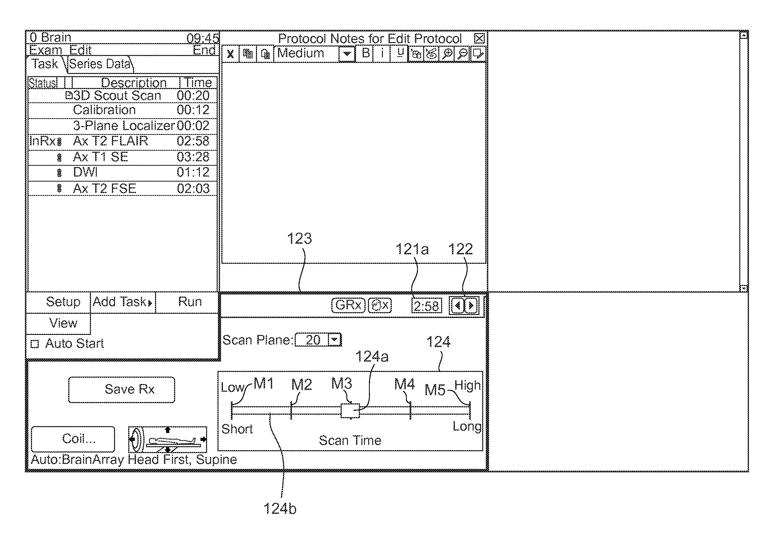
[0078]The slider bar 124 for selecting the width of a field of view FOV is displayed in a display window 123. The slider bar 124 has a slider 124a, and a bar 124b for defining a range in which the slider 124a is movable. The bar 124b is marked with scales M1 through M5 for enabling the width of the field of view FOV to be selected from within five choices...


PUM


Abstract

A scan condition setting apparatus sets a scan condition used upon scanning a subject. The apparatus includes a selection device having a plurality of combinations of scan times and image quality and selecting one from within the combinations according to a manipulation of an operator, and a scan condition storage device for storing scan conditions corresponding to the combinations of the scan times and image quality therein. The scan condition corresponding to the combination of the scan times and image quality selected by the selection device is set as the scan condition used when the subject is scanned.

Description

CROSS REFERENCE TO RELATED APPLICATIONS[0001]This application claims the benefit of Japanese Patent Application No. 2009-255618 filed Nov. 9, 2009, which is hereby incorporated by reference in its entirety.BACKGROUND OF THE INVENTION[0002]The present invention relates to a scan condition setting apparatus for setting a scan condition, and a medical apparatus.[0003]An operator needs to set an imaging or scan condition upon imaging a subject. As the number of scan conditions to be set increases, a burden on the operator also becomes large. There has therefore been proposed a method for making it possible to quickly and easily select and set scan parameters or the like (refer to Japanese Unexamined Patent Publication No. 2003-225222).[0004]The method according to the above-referenced document enables adjustments of parameters dominant over image contrast every scanning. However, in general, it is not easy to understand the degree of change of the image contrast where the parameters are...

Claims


Application Information

Patent Timeline
IPC IPC(8): G06F3/048
CPCG01R33/546G01R33/543G01R33/5602
Inventor SUZUKI, KENJICHOPPIN, ANTOINE
Owner GE MEDICAL SYST GLOBAL TECH CO LLC
Why Eureka
Try Eureka