Heavy duty tire

a technology of pneumatic tires and rims, applied in the direction of tire beads, heavy-duty vehicles, vehicle components, etc., can solve the problems of wear of both tires and rims

Inactive Publication Date: 2011-05-19
VENKATARAMANI GAYATHRI +2
View PDF19 Cites 25 Cited by
  • Summary
  • Abstract
  • Description
  • Claims
  • Application Information

AI Technical Summary

Benefits of technology

[0013]“Design rim” means a rim having a specified configuration and width. For the purposes of this specification, the design rim and design rim width are as specified by the industry standards in effect in the location in which the tire is made. For example, in the United States, the design rims are as spec

Problems solved by technology

The two modes of deformation result in rubbing of the chafer ag

Method used


Image

  • Heavy duty tire
  • Heavy duty tire
  • Heavy duty tire

Examples


Embodiment Construction

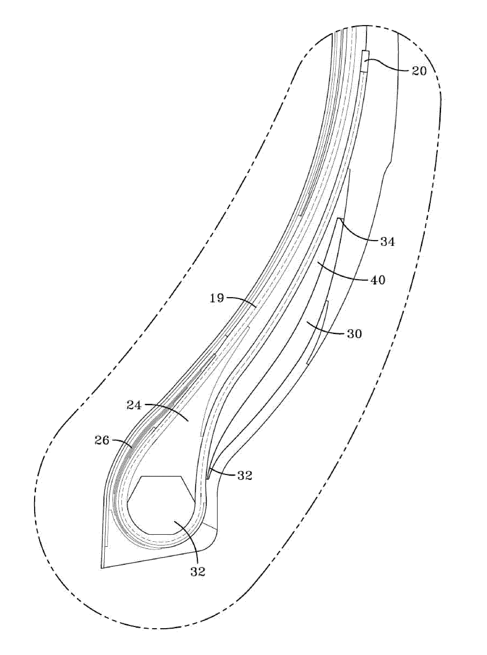
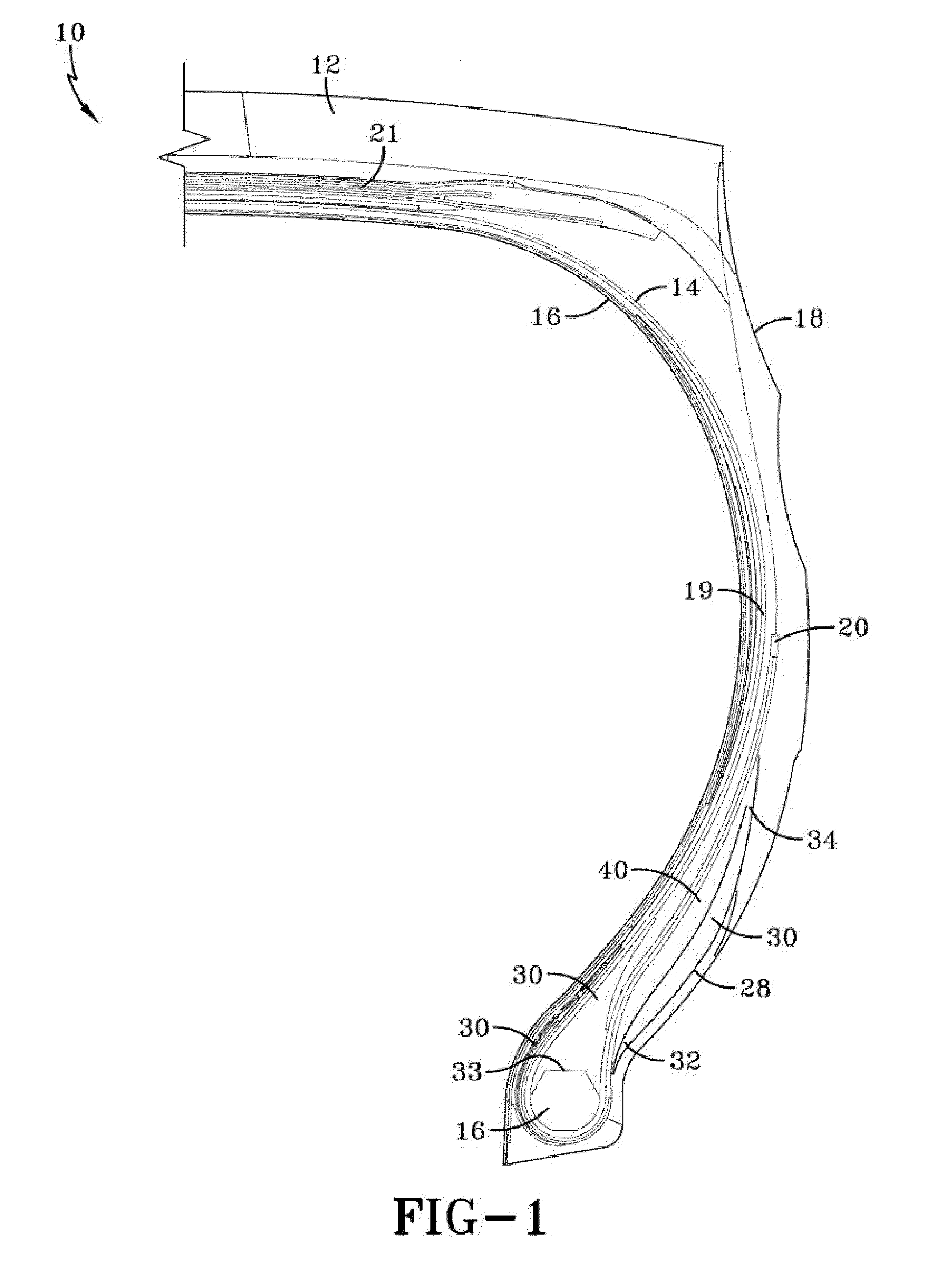
[0030]With reference to FIGS. 1 and 2, a cross-sectional view of one half of a tire of the present invention 10 is illustrated. The tire 10 has a carcass 14 which includes a crown region having a radially outer tread 12 disposed over the crown region of the carcass 14. The outer surface of the tread may further include a plurality of lands and grooves or a plurality of tread blocks and grooves, as commonly known to those skilled in the art. The carcass further includes an inner liner 16 that covers the entire interior facing surface of the tire carcass and serves to hold the air or gas mixture that is used to inflate the tire. The inner liner of the tire is typically made of butyl rubber. The carcass 14 further includes a pair of tire sidewalls 18 which extend radially inward from the outer radial surface of the of the tire carcass, terminating in the vicinity of a pair of inextensible beads 16.

[0031]The annular beads 16 illustrate an asymmetrical cross sectional shape having a lowe...


PUM


Abstract

A pneumatic tire construction is described suitable for severe loading conditions. The tire includes a bead portion further having an apex which extends radially outward of the bead core, and a first turnup pad located adjacent said chafer, and a second turnup pad located adjacent said first turnup pad, wherein the first turnup pad has a G′ less than the G′ of the second turnup pad. Alternatively, the first turnup pad may be located adjacent to the rim flange and the second turnup pad may be located axially inward of the first pad. The second turnup pad is preferably thicker and longer than the first turnup pad.

Description

TECHNICAL FIELD[0001]This invention relates to heavy duty pneumatic tires such as are commonly used on earthmoving equipment, aircraft, and agricultural tires.BACKGROUND[0002]The invention concerns the reduction of rim chafing in Off-The-Road tires of radial construction that are used in heavily loaded vehicles. The lower sidewall of a typical radial OTR construction consists of a ply around the bead and chipper reinforcements that restrict the circumferential deformation of the ply. Under the action of loads, the lower sidewall of the tire bends over the rim flange, and the ply reinforcement rotates in the circumferential direction. The two modes of deformation result in rubbing of the chafer against the rim flange resulting in wear of both the tire and rim. Chafing can be minimized by using reinforcements in the lower sidewall, but this reduction is not very significant. Thus it is desired to have an improved tire design to reduce the rim chafing of the tire against the rim.DISCLO...

Claims


Application Information

Patent Timeline
IPC IPC(8): B60C15/00
CPCB60C15/06Y10T152/10819B60C2015/0621B60C2200/06
Inventor VENKATARAMANI, GAYATHRIBACHIR, MOHAMAD AFIFWELLS, DALE EUGENE
Owner VENKATARAMANI GAYATHRI
Why Eureka
Try Eureka