
Method and system for model based control of heavy duty gas turbine

a gas turbine and model technology, applied in the direction of machine/engine, process and machine control, nuclear elements, etc., can solve the problems of several inefficiencies, inconsistencies in the design process, and limited operation of the turbine, so as to reduce the risk of constraint violation

Active Publication Date: 2007-05-15
GENERAL ELECTRIC CO
View PDF14 Cites 75 Cited by
  • Summary
  • Abstract
  • Description
  • Claims
  • Application Information

AI Technical Summary

Benefits of technology

[0012]In another aspect, the optimizer/controller reduces the risk of constraint v...

Problems solved by technology

Gas turbine behavior is generally described by highly non-linear models and its operation is limited by several operational constraints.
Accordingly, this separate design of the operations and controls together with simulations to verify the efficacy of the separate design gives rise to several inefficiencies.
The operation and control are designed separately (and often substantially independently) and then coupled together giving rise to integration errors and other inconsistencies in the design process.
Accordingly, making any changes is a complex process since the changes have to be carefully coordinated in the design of both the operations and the control systems.
Therefore, any specific changes requested by customers also need to be implemented using this cumbersome and relatively disjointed procedure whereby the operations and controls are separately redesigned and then coordinated by simulation or other verification to ensure the integrity of the changes introduced.
Accordingly, it is difficult to expediently provide the specific changes that may be desired by specific customers.
Furthermore, the operational path has to be designed in advance which prevents the operational design from being optimized based on run time conditions or parameters.
Therefore, each specific machine cannot be easily optimized by using this apriori design of the operation path or schedule for the gas turbine.
Likewise, dynamic stability assessment and disturbance rejection via coordinated control actions is not easy to accomplish.
In addition, the complex interactions between independently designed operations and controls gives rise to maintenance problems since any maintenance related changes have to be properly coordinated between the operations and controls systems.

Method used


Image

  • Method and system for model based control of heavy duty gas turbine
  • Method and system for model based control of heavy duty gas turbine
  • Method and system for model based control of heavy duty gas turbine

Examples


Embodiment Construction

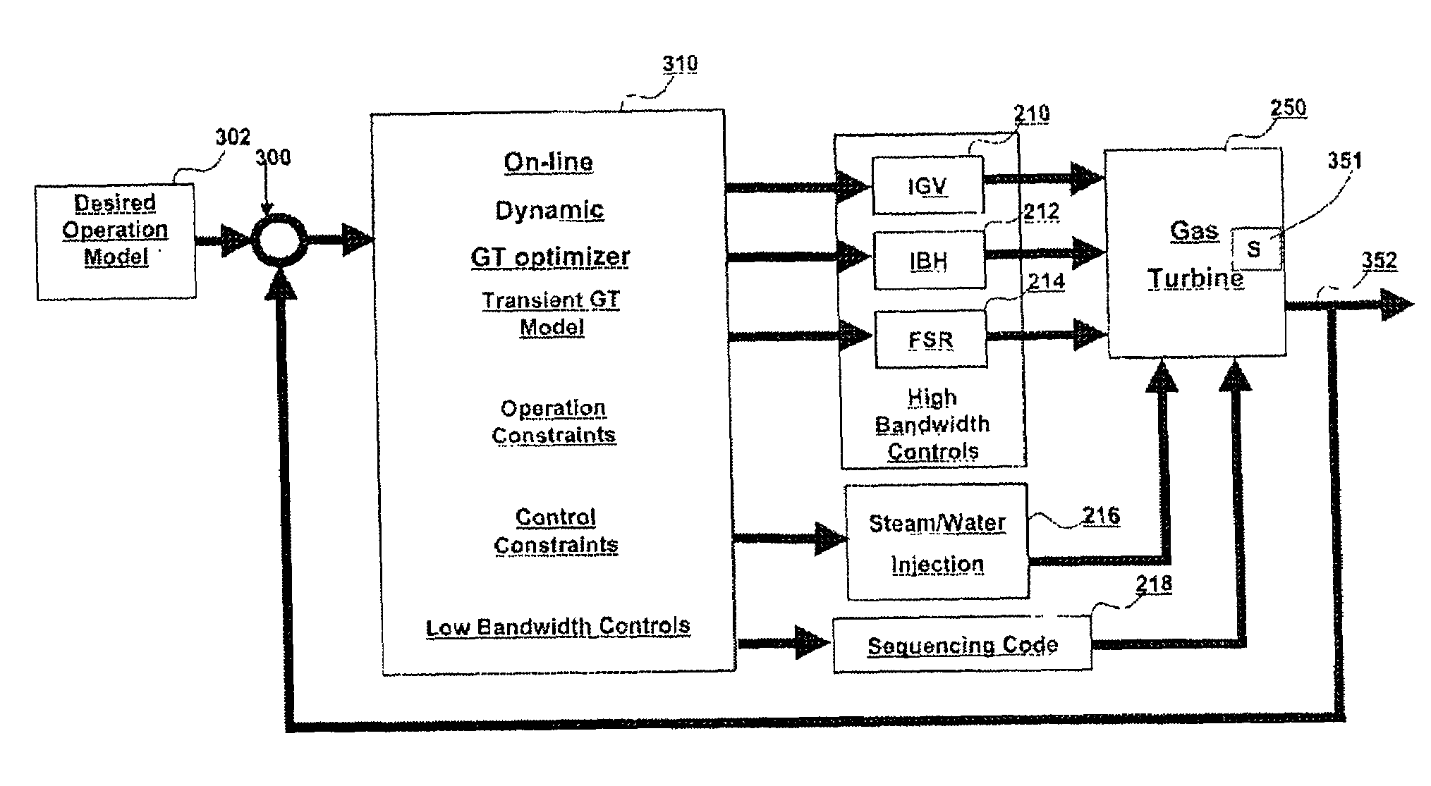
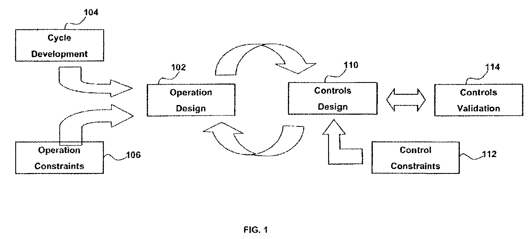
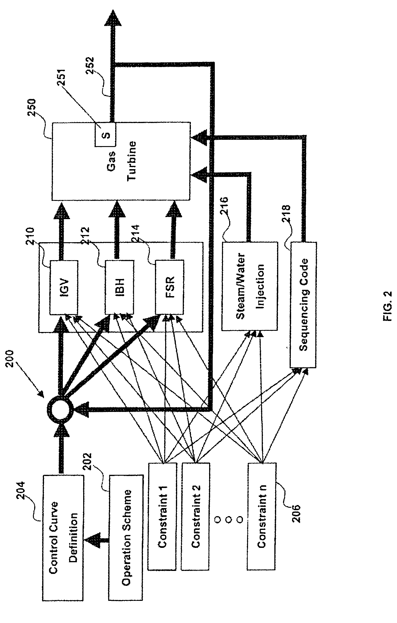
[0032]FIG. 1 is a block diagram illustrating a design process for the operations and controls of a gas turbine. An operation design process 102 defines operations schedules for operating a gas turbine. The operation design process 102 inputs operations related constraints 106 and an operations model developed in a model development process 104 (in which a thermodynamic model, both steady state and transient, of the gas turbine is developed that serves as the basis for the operations model). The operations design process 102 then generates the operation schedules based on the operations model and the operations constraints in order to optimize the operational performance of the gas turbine. Examples of operational constraints are provided further herein with respect to the discussion of the exemplary gas turbine model discussed further. A typical operations model (defined in the cycle development process 104) includes an objective function that is a transfer function that seeks to op...


PUM


Abstract

A method and system of designing the operations and controls of a gas turbine, includes generating an operations model for the gas turbine including at least one objective function and defining operations and control constraints for the operations model of the gas turbine. An online dynamic optimizer / controller dynamically optimizes and controls operation of the gas turbine using model based control based on the operations model and the operations and control constraints. The model based control may include model predictive control.

Description

BACKGROUND OF THE INVENTION[0001]This invention relates generally to a more efficient design of the operation and control of a gas turbine. More specifically, the present invention is directed to a method, system, and software for a model based control of a heavy duty gas turbine that integrates the design of the operations and the controls for the gas turbine.[0002]Gas turbine behavior is generally described by highly non-linear models and its operation is limited by several operational constraints. Enforcement of the constraints is typically mandatory and good dynamic behavior throughout the operating space must be ensured. Generally, gas turbines are operated using pre-defined operating schedules which attempt to provide an optimal operating strategy. These operating schedules are validated using a dynamic simulation of the turbine with the operating schedule and a separately designed control system for operation of the turbine. Accordingly, the operation and control design are d...

Claims


Application Information

Patent Timeline
IPC IPC(8): G06G7/48G05B13/04
CPCF02C9/28G05B13/048F05D2270/71F05D2270/44F05D2270/70
Inventor RENOU, STEPHANESHAH, MINESH ASHOK
Owner GENERAL ELECTRIC CO
Learn More