System and Method for Powering Accessories in a Hybrid Vehicle

a hybrid vehicle and accessory technology, applied in the direction of battery/fuel cell control arrangement, capacitor propulsion, battery/cell propulsion, etc., can solve the problems of inefficiency introduced into the vehicle, inefficiency introduced in the hybrid vehicle, and inefficiency in the overall cost of the vehicl

Inactive Publication Date: 2007-05-10
SHEPPARD MULLIN RICHTER & HAMPTON
View PDF9 Cites 70 Cited by
  • Summary
  • Abstract
  • Description
  • Claims
  • Application Information

AI Technical Summary

Benefits of technology

[0008] Accordingly, as aspect of the present invention involves a vehicle power system for a heavy-duty hybrid vehicle including an engine compartment and a drive shaft. The vehicle power system includes a main power unit configured to supply a DC power to the heavy-duty hybrid vehicle and located in the engine compartment; an electric propulsion motor to propel the heavy-duty hybrid vehicle using the drive shaft; a DC bus electrically coupled with the main power unit, the DC bus configured to receive the DC power from the main power unit; a vehicle accessory traditionally powered directly from an internal combustion engine of a conventional heavy-duty vehicle and requiring more than 1 kilowatt of power, the vehicle access

Problems solved by technology

In implementing either of the above solutions to power vehicle accessories, however, inefficiencies are introduced into a vehicle.
These inefficiencies may affect the cost of the vehicle, the performance of the vehicle, or both.
For example, if a hybrid or electric vehicle includes electric versions of one or more accessories, the inefficiency introduced in the hybrid vehicle is in the overall cost of the vehicle.
The increased cost arises because the electric version of an accessory must initially be developed and tested.
Additionally, the cost of the electric version of the accessory will typically remain high over a period of one to several years because vehicles which use the electric version of the accessory do not have the high production quantities of conventional vehicles.
Conversely, if a hybrid vehicle

Method used


Image

  • System and Method for Powering Accessories in a Hybrid Vehicle
  • System and Method for Powering Accessories in a Hybrid Vehicle
  • System and Method for Powering Accessories in a Hybrid Vehicle

Examples


Embodiment Construction

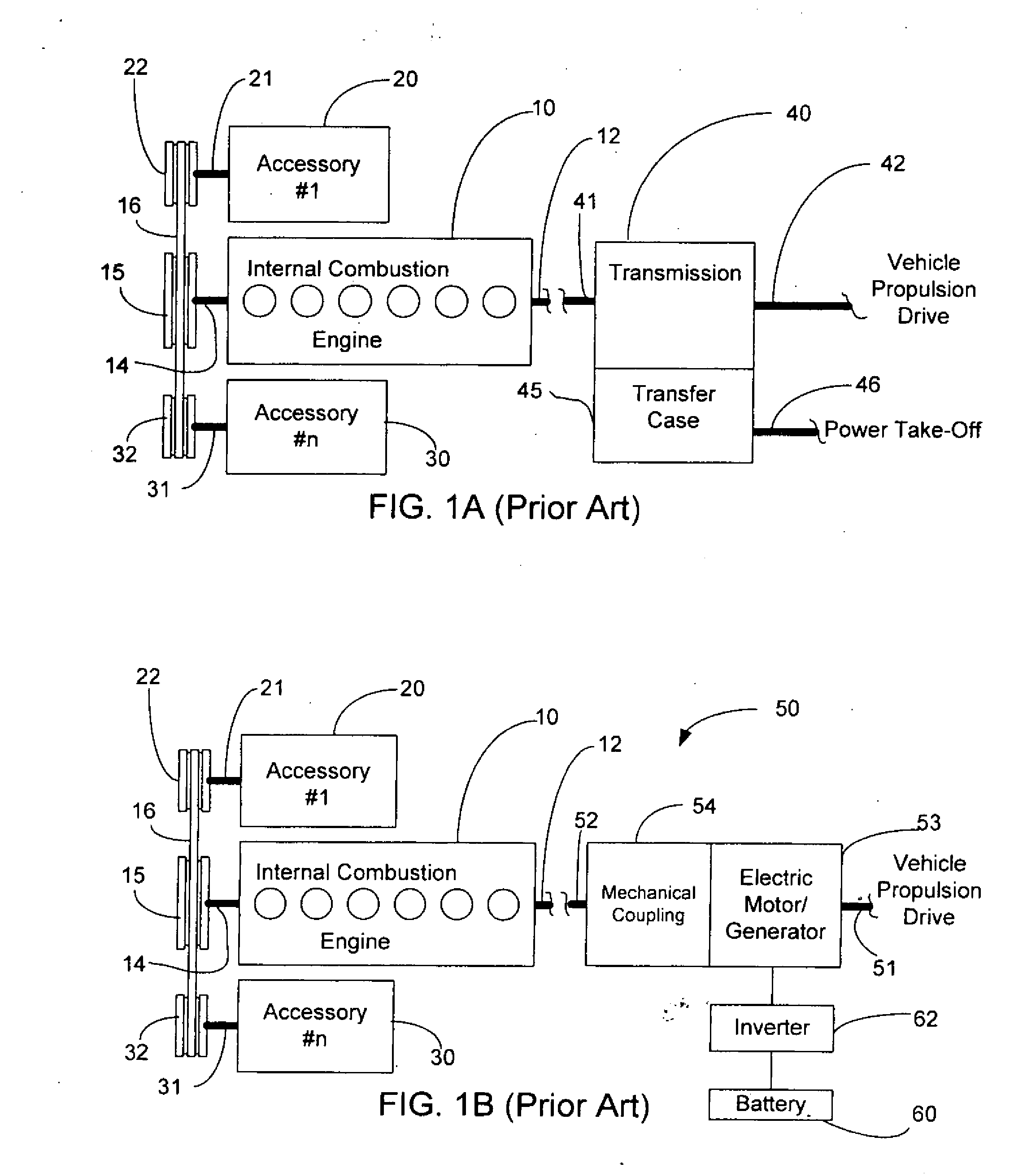
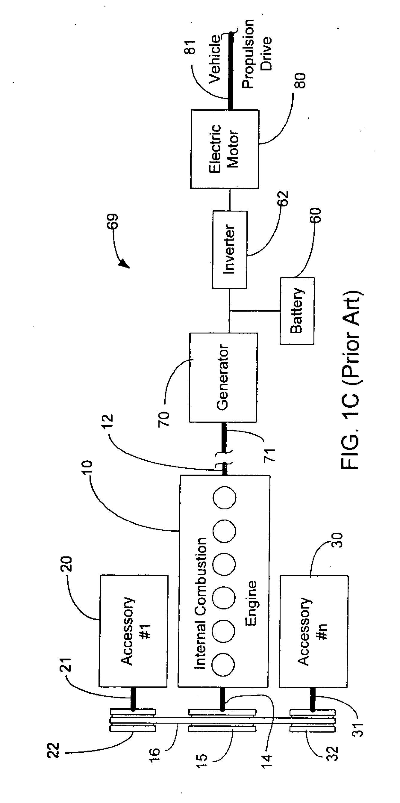
[0024] Turning in detail to the drawings, FIGS. 1a-c illustrate systems of driving vehicle accessories as practiced in the prior art. FIG. 1a schematically illustrates a conventional vehicle 9 (e.g., a passenger car, a light truck, a heavy-duty vehicle such as a refuse collection ‘truck or transit bus, or other type of vehicle) having an internal combustion engine 10. The internal combustion engine has two output shafts 12, 14. The first output shaft 12 is coupled to an input shaft 41 of a transmission 40 that may be used to propel the vehicle using a drive shaft 42. Alternatively, the power provided to the transmission 40 may be directed into a transfer case 45 and used to drive a power take-off shaft 46. The power take-off shaft 46 may be used, for example, to drive an additional axle in a four-wheel drive vehicle or to drive a hydraulic pump used in conjunction with heavy-duty equipment such as the lift mechanism in a dump truck or a compactor in a refuse collection truck.

[0025]...


PUM


Abstract

A heavy-duty hybrid vehicle power system includes a main power unit located in an engine compartment; an electric propulsion motor; a DC bus that receives DC power from the main power unit; a vehicle accessory traditionally powered directly from an internal combustion engine of a conventional heavy-duty vehicle and requiring more than 1 kilowatt of power; an electric accessory motor, which is electrically coupled with the DC bus and mechanically coupled with the vehicle accessory, configured to supply power to the vehicle accessory, and the electric accessory motor and vehicle accessory carried by the heavy-duty vehicle either inside or outside of the engine compartment; and at least one of an ultracapacitor pack and a fly wheel coupled with the DC bus and configured to store power when the main power unit is on and supply power in place of the main power unit when the main power unit is off.

Description

CROSS-REFERENCE TO RELATED APPLICATION [0001] This application is a continuation-in-part of U.S. patent application Ser. No. 11 / 250,865, filed Oct. 14, 2005, which is a divisional application of U.S. patent application Ser. No. 10 / 160,877, filed May 31, 2002, now U.S. Pat. No. 7,119,454 issued Oct. 10, 2006, which are all hereby incorporated by in their entirety by reference.FIELD OF THE INVENTION [0002] The field of the present invention is generally motor vehicles, and in particular systems within motor vehicles that power vehicle accessories. BACKGROUND [0003] In conventional vehicles, i.e., vehicles that are neither hybrid vehicles nor electric vehicles, accessories such as hydraulic pumps, water pumps, vacuum pumps, and compressors for air brakes or air conditioning systems are powered directly from the internal combustion engine. The power required by these accessories may be steady over extended periods of time, as in the case of a water pump that is used to help cool the eng...

Claims


Application Information

Patent Timeline
IPC IPC(8): B60L1/00
CPCB60K6/46B60K6/48B60L1/003B60L11/005B60L11/123B60L11/14B60L11/1887Y02T10/6217Y02T10/6221Y02T10/7022Y02T10/7077Y02T90/34B60L50/16B60L50/40B60L50/61B60L58/40Y02T10/62Y02T10/70Y02T10/7072Y02T90/40
Inventor CHIAO, SHENGSTONE, KEVIN T.
Owner SHEPPARD MULLIN RICHTER & HAMPTON
Why Eureka
Try Eureka