Systems for generating useful energy from vehicle motion

a technology for generating useful energy and vehicle motion, applied in the direction of electric generator control, electric motor propulsion transmission, machines/engines, etc., can solve the problems of limited maximum output, price inflation of various fossil fuels, and countries struggling to prepare, and achieve the effect of generating useful energy

Inactive Publication Date: 2009-06-02
VALENTINO JOSEPH A
View PDF42 Cites 69 Cited by
  • Summary
  • Abstract
  • Description
  • Claims
  • Application Information

AI Technical Summary

Problems solved by technology

Moreover, countries are struggling to prepare for the expected depletion of the world's petroleum supply and the resulting price inflation of various fossil fuels.
Devices such as photovoltaic cells and windmills have been engineered over several decades; however, their limited maximum output often makes them prohibitively expensive.
First of all, existing systems require the installation of extensive combinations of mechanical gears and linkages below the roadway. Some systems even require the installation of sensitive electronics and other components below the roadway. Therefore, these systems are very difficult and expensive to install in existing roadways. They also greatly increase the cost of constructing new roadways. Moreover, because so many components are installed below the roadway, they may be easily damaged due to adverse weather, water damage, and the negative physical effects of heavy traffic. Accordingly, existing systems are extremely expensive to repair and maintain, in the event of both normal wear-and-tear and periodic component failure due to occasional, extreme impacts.
In addition, existing systems are generally energy-inefficient and insufficiently cost effective.
Existing systems do not capture a significant amount of energy upon the impact of a passing vehicle, and they also suffer from other system-wide inefficiencies.
The existing methods of energy conversion fail to fully exploit the potential of the captured energy to generate useful electrical energy.
Thus, existing systems and methods provide relatively little energy output and therefore fail to sufficiently outweigh the costs of their installation, maintenance, and repair.

Method used


Image

  • Systems for generating useful energy from vehicle motion
  • Systems for generating useful energy from vehicle motion
  • Systems for generating useful energy from vehicle motion

Examples


Embodiment Construction

[0020]Reference will now be made in detail to the presently preferred embodiment of the invention, an example of which is illustrated in the accompanying drawings. Wherever possible, the same reference numbers will be used throughout the drawings to refer to the same or like parts.

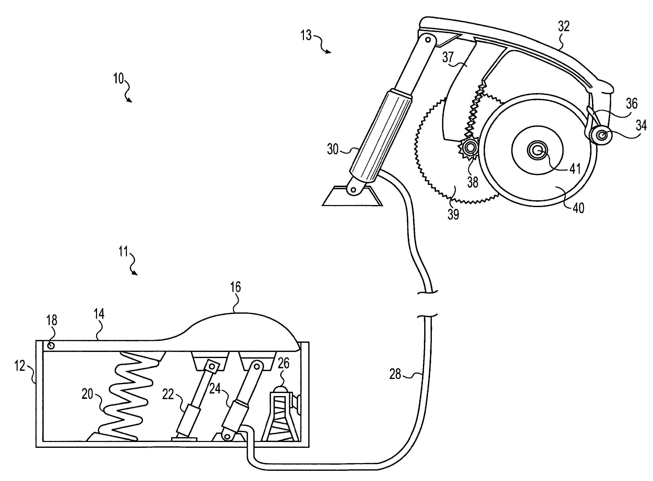
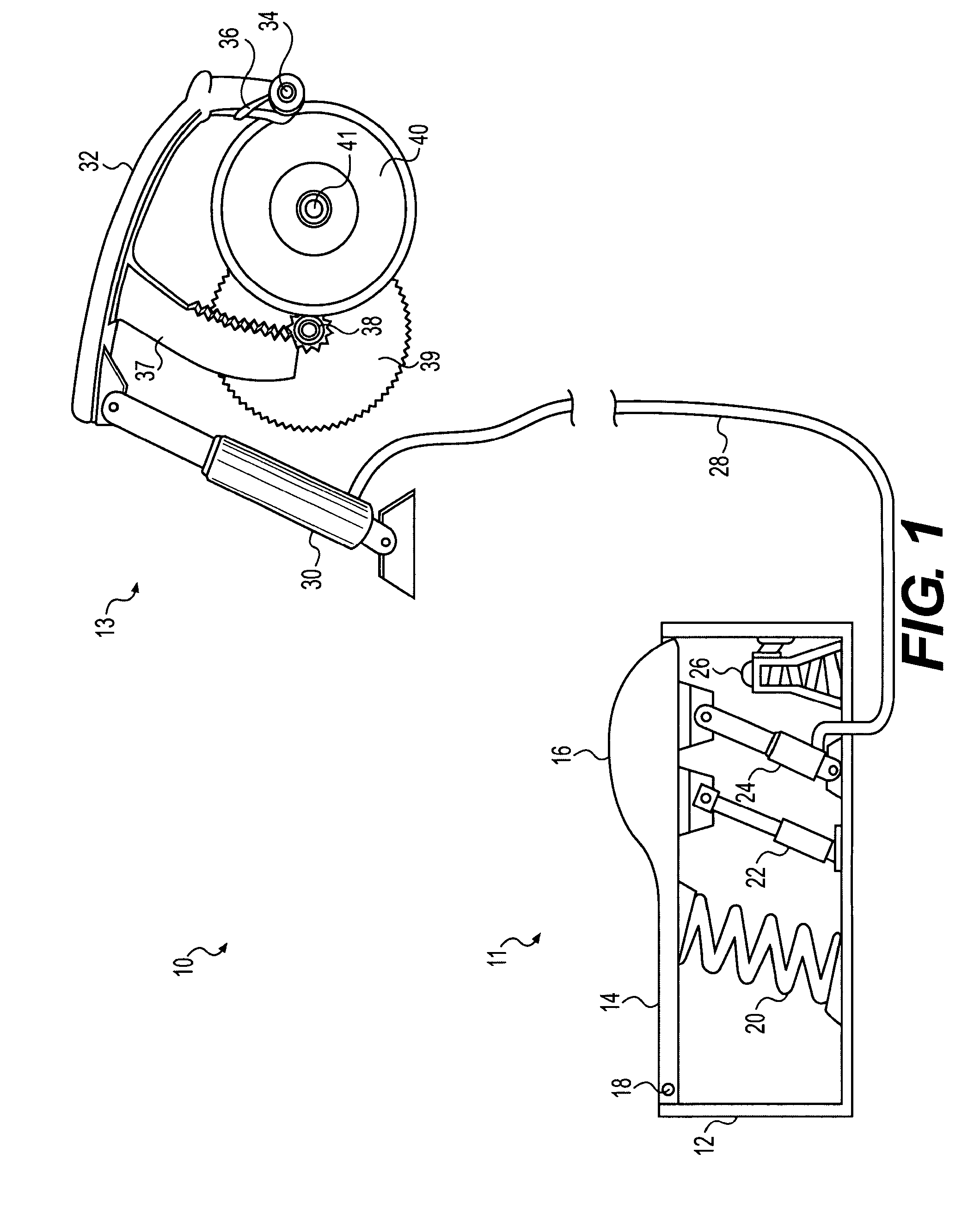
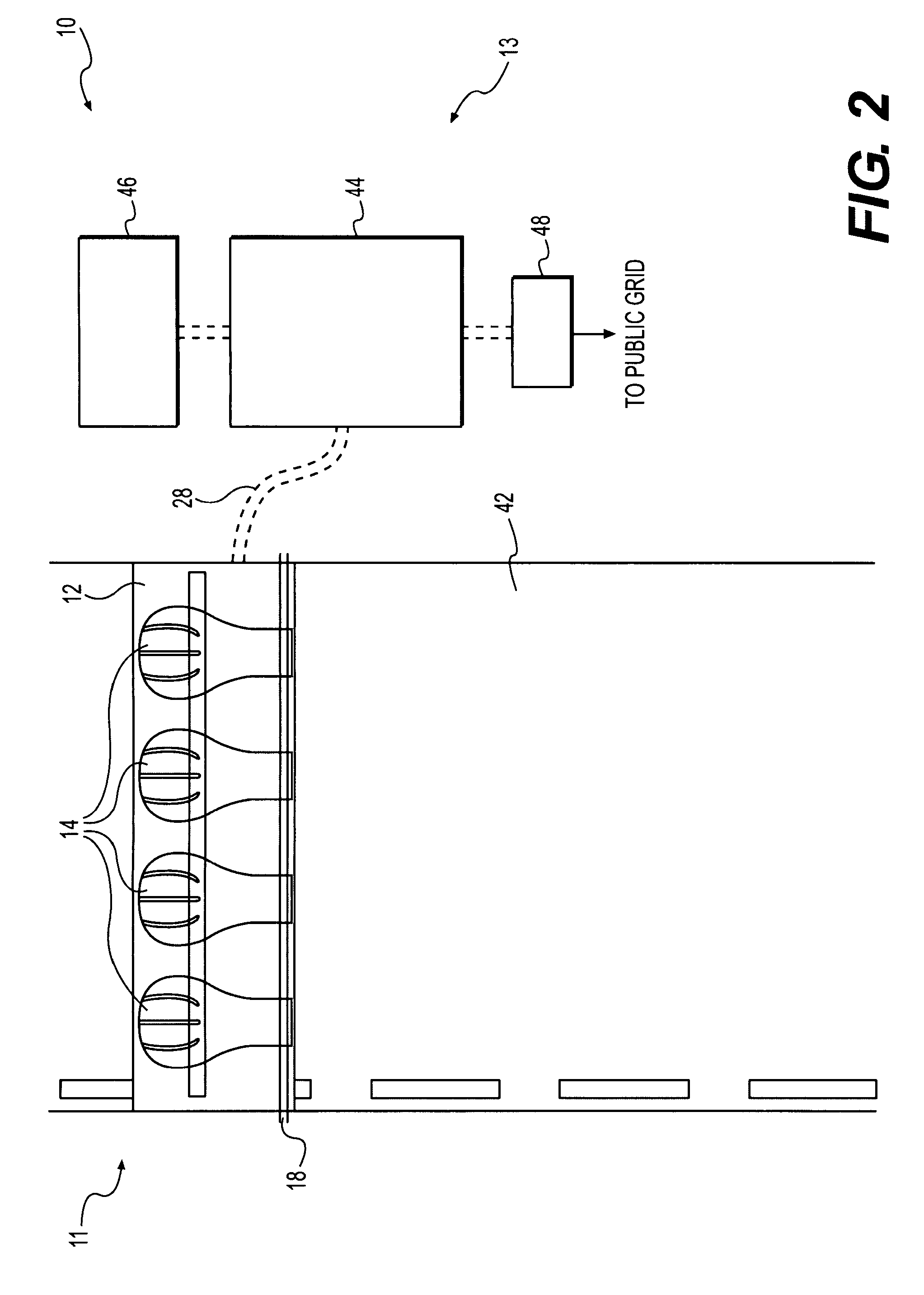
[0021]Referring to FIG. 1, a preferred embodiment is disclosed including a system 10 for generating useful energy from vehicle motion generally includes a master fluid cylinder and tiger pawl assembly 11 and a secondary cylinder and lever assembly 13.

[0022]The master fluid cylinder and tiger pawl assembly 11 preferably includes an underground box 12 that is configured to be installed below the surface of a roadway. The underground box 12 preferably is made out of approximately ½ to ¾ inch steel plate, or any other material sufficiently strong and resilient to support the cyclical loading of various vehicle weights. The underground box 12 has an upper surface including a movable plate, or tiger pawl 14, tha...


PUM


Abstract

A system for generating useful energy from vehicle motion. The system includes: a projection projecting above a road surface, pivotably mounted to the road surface to be pushed downward against an upward bias, by a vehicle tire passing over an upper surface of the projection; a master fluid cylinder mechanically linked to the projection; a fluid transfer device connected to the master fluid cylinder; a secondary fluid cylinder, communicating with the master fluid cylinder via the fluid transfer device; and a lever configured to transfer motion from the secondary fluid cylinder to a flywheel shaft, the flywheel shaft having a distal end coupled to an electric generator.

Description

FIELD OF THE INVENTION[0001]In general, the present disclosure relates to the generation of useful energy from vehicle motion, and more specifically, to systems for converting vehicle motion into rotation of an off-road flywheel shaft connected to an electric generator.BACKGROUND OF THE INVENTION[0002]Recently, countries around the world have become more sensitive to the effects of releasing pollutants, such as carbon monoxide, carbon dioxide, and nitrogen dioxides, into the air. Moreover, countries are struggling to prepare for the expected depletion of the world's petroleum supply and the resulting price inflation of various fossil fuels. Because of this, there has been an increased emphasis on the development and refinement of “renewable” and alternative sources of energy. For example, the collection and conversion of naturally occurring solar and wind energy has long been pursued. Devices such as photovoltaic cells and windmills have been engineered over several decades; however...

Claims


Application Information

Patent Timeline
Patent Type & Authority Patents(United States)
IPC IPC(8): F03G3/00H02K7/00
CPCB60L7/16B60L8/00B60L11/16B60L11/1816F03G7/08H02J7/02Y02T10/7027H02J2001/004Y02T10/7005Y02T10/7033Y02T10/7083Y02T90/14Y02T90/16H02J7/14B60L50/30B60L53/14H02J2300/30Y02T10/70Y02T10/7072H02J5/00
Inventor VALENTINO, JOSEPH A.
Owner VALENTINO JOSEPH A
Why Eureka
Try Eureka