Variable speed transmission for a rotary wing aircraft

Active Publication Date: 2006-11-30
ACRESSO SOFTWARE +1
View PDF8 Cites 73 Cited by
  • Summary
  • Abstract
  • Description
  • Claims
  • Application Information

AI Technical Summary

Benefits of technology

[0012] The present invention therefore provides a variable speed gearbox system for a rotary-wing aircraft that provides a “high rotor speed mode

Problems solved by technology

The forward airspeed of a conventional rotary wing aircraft is limited by a number of factors.
Among these is the tendency of the retreating blade to stall at high forward airspeeds.
As the forward airspeed increases, the airflow velocity across the retreating blade slows such that the blade may approach a stall condition.
This dissymmetry of lift may create an unstable condition if not equalized across the advancing and retreating sectors of the rotor disc.
However, as the forward airspeed is increased beyond a given point for a given rotor rpm, the flapping

Method used


Image

  • Variable speed transmission for a rotary wing aircraft
  • Variable speed transmission for a rotary wing aircraft
  • Variable speed transmission for a rotary wing aircraft

Examples


Embodiment Construction

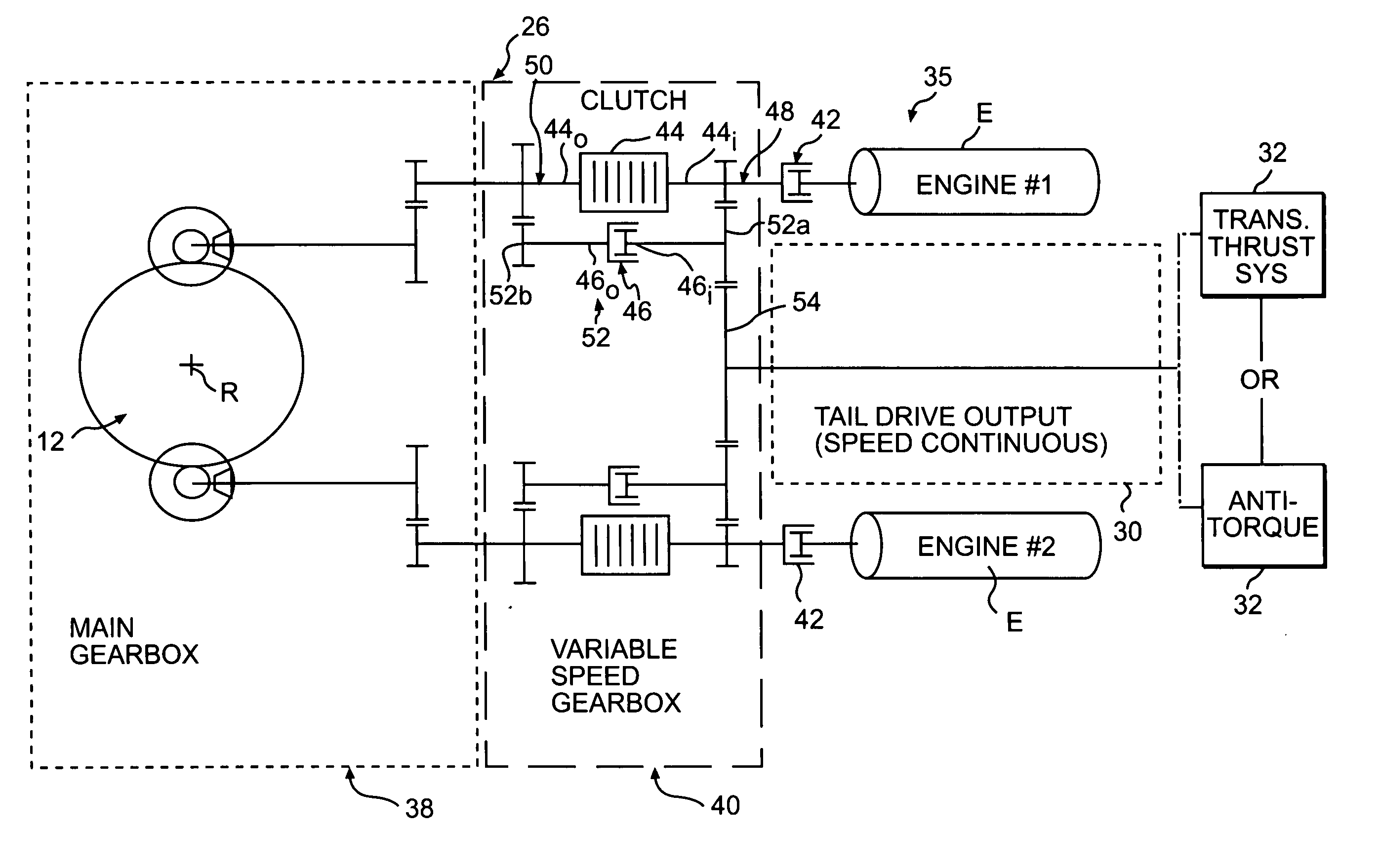
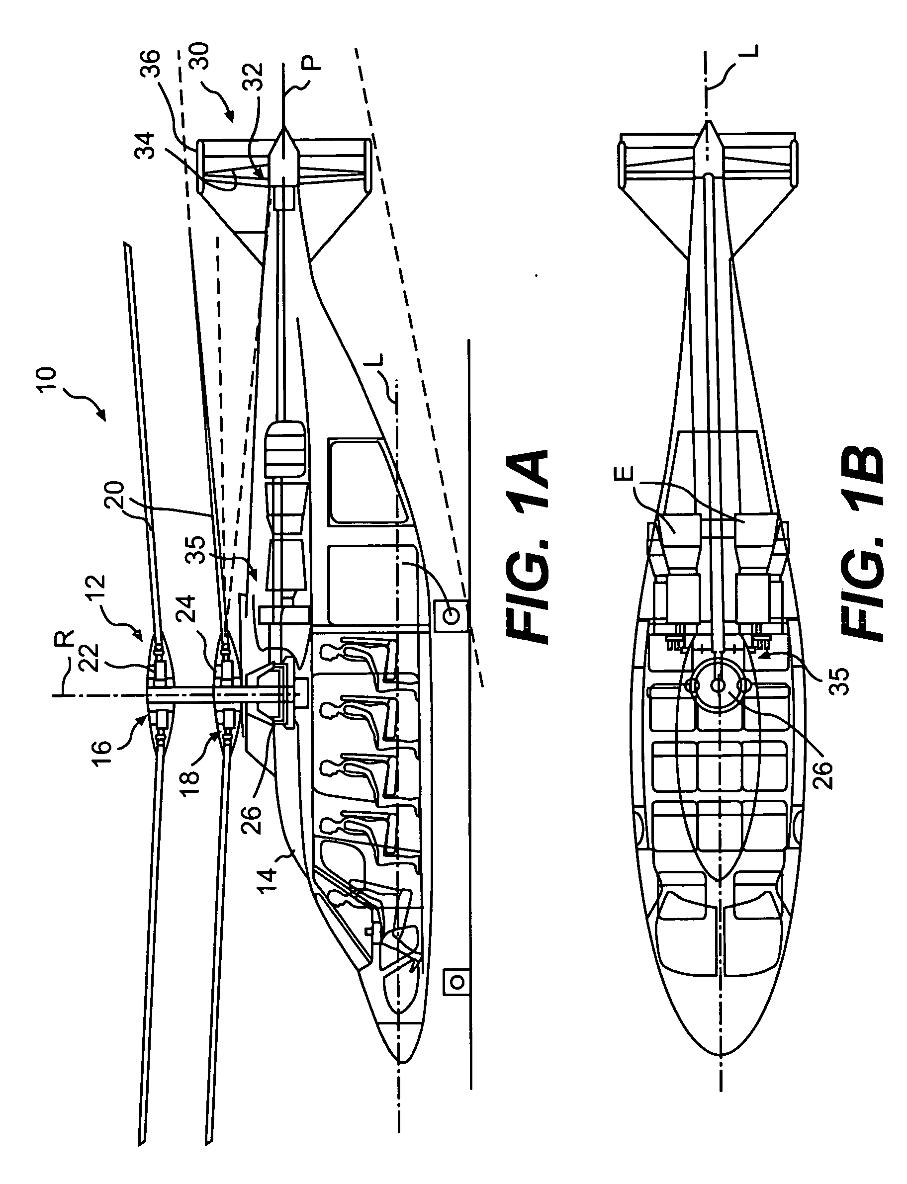
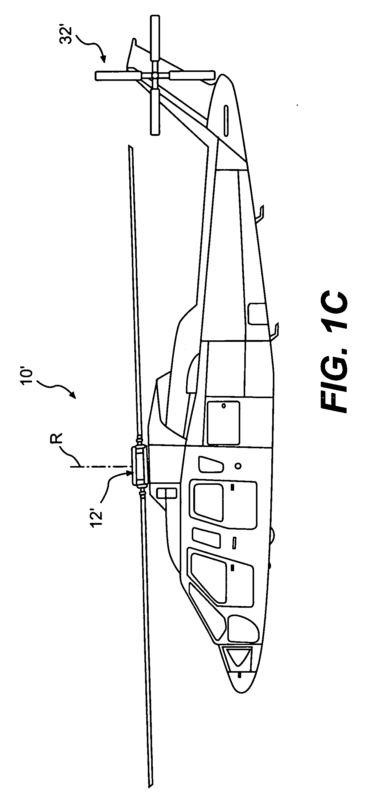
[0020]FIGS. 1A and 1B illustrate a vertical takeoff and landing (VTOL) rotary-wing aircraft 10 having a main rotor system 12. The main rotor system 12 is preferably a dual, counter-rotating, coaxial rotor system, however, any other rotor system known in the art including, but not limited to, single, tandem and dual rotor systems may also be used with the present invention. That is, although the present invention is being described in combination with a high speed compound rotary wing aircraft, other aircraft configurations, including a more conventional configuration with a single main rotor system 12′ and an anti-torque tail rotor system 32′ (FIG. 1C) will also benefit from the present invention.

[0021] As shown, the aircraft 10 includes an airframe 14 which supports the main rotor system 12. The aircraft 10 may also incorporate a tail drive system 30. The tail drive system 30 is preferably a translational thrust system 32 that provides translational thrust generally parallel to an...


PUM


Abstract

A transmission gearbox for a rotary-wing aircraft includes a main gearbox and a variable speed gearbox in meshing engagement with the main rotor gearbox. The variable speed gearbox permits at least two different RPMs for the main rotor system without disengaging the engine(s) or changing engine RPMs. The variable speed gearbox includes a clutch, preferably a multi-plate clutch, and a freewheel unit for each engine. A gear path drives the main gearbox in a “high rotor speed mode” when the clutch is engaged to drive the main rotor system at high rotor rpm for hover flight profile. A reduced gear path drives the main gearbox in a “low rotor speed mode” when the clutch is disengaged and power is transferred through the freewheel unit, to drive the main rotor system at lower rotor rpm for high speed flight. The variable speed gearbox may be configured for a tail drive system that operates at a continuous speed, a tail drive system that changes speed with the main rotor shaft or for no tail drive system.

Description

BACKGROUND OF THE INVENTION [0001] The present invention relates to a rotary-wing aircraft, and more particularly to a rotary wing transmission gearbox system which provides variable speeds to facilitate high speed and low speed flight profiles. [0002] The forward airspeed of a conventional rotary wing aircraft is limited by a number of factors. Among these is the tendency of the retreating blade to stall at high forward airspeeds. As the forward airspeed increases, the airflow velocity across the retreating blade slows such that the blade may approach a stall condition. In contrast, the airflow velocity across the advancing blade increases with increasing forward speed. Dissymmetry of lift is thereby generated as forward air speed increases. [0003] This dissymmetry of lift may create an unstable condition if not equalized across the advancing and retreating sectors of the rotor disc. Typically, blade flapping and feathering are utilized to substantially equalize the lift. [0004] Ho...

Claims


Application Information

Patent Timeline
IPC IPC(8): B64D35/00B64C27/00
CPCB64C27/10B64C27/12Y10T74/19051B64C27/82B64C2027/8236B64C27/22
Inventor PALCIC, PETER XAVIERGARCIA, TODDGMIRYA, YURIY
Owner ACRESSO SOFTWARE
Why Eureka
Try Eureka