Support stand for flat-panel display monitor

a flat-panel display and support bracket technology, applied in the field of support brackets for flat-panel display monitors, can solve the problem of insufficient rigidity to ensure the connection between the base and the bas

Inactive Publication Date: 2011-05-19
HONG FU JIN PRECISION IND (SHENZHEN) CO LTD +1
View PDF6 Cites 25 Cited by
  • Summary
  • Abstract
  • Description
  • Claims
  • Application Information

AI Technical Summary

Problems solved by technology

However, since, during assembly, the hook is resiliently moved to be received in the slot of the bracket, whereby the hook must be sufficiently elastic to be able to resiliently move, and thereby may provide insufficient rigidity to ensure firm connection between the base and the bracket.

Method used


Image

  • Support stand for flat-panel display monitor
  • Support stand for flat-panel display monitor
  • Support stand for flat-panel display monitor

Examples


Embodiment Construction

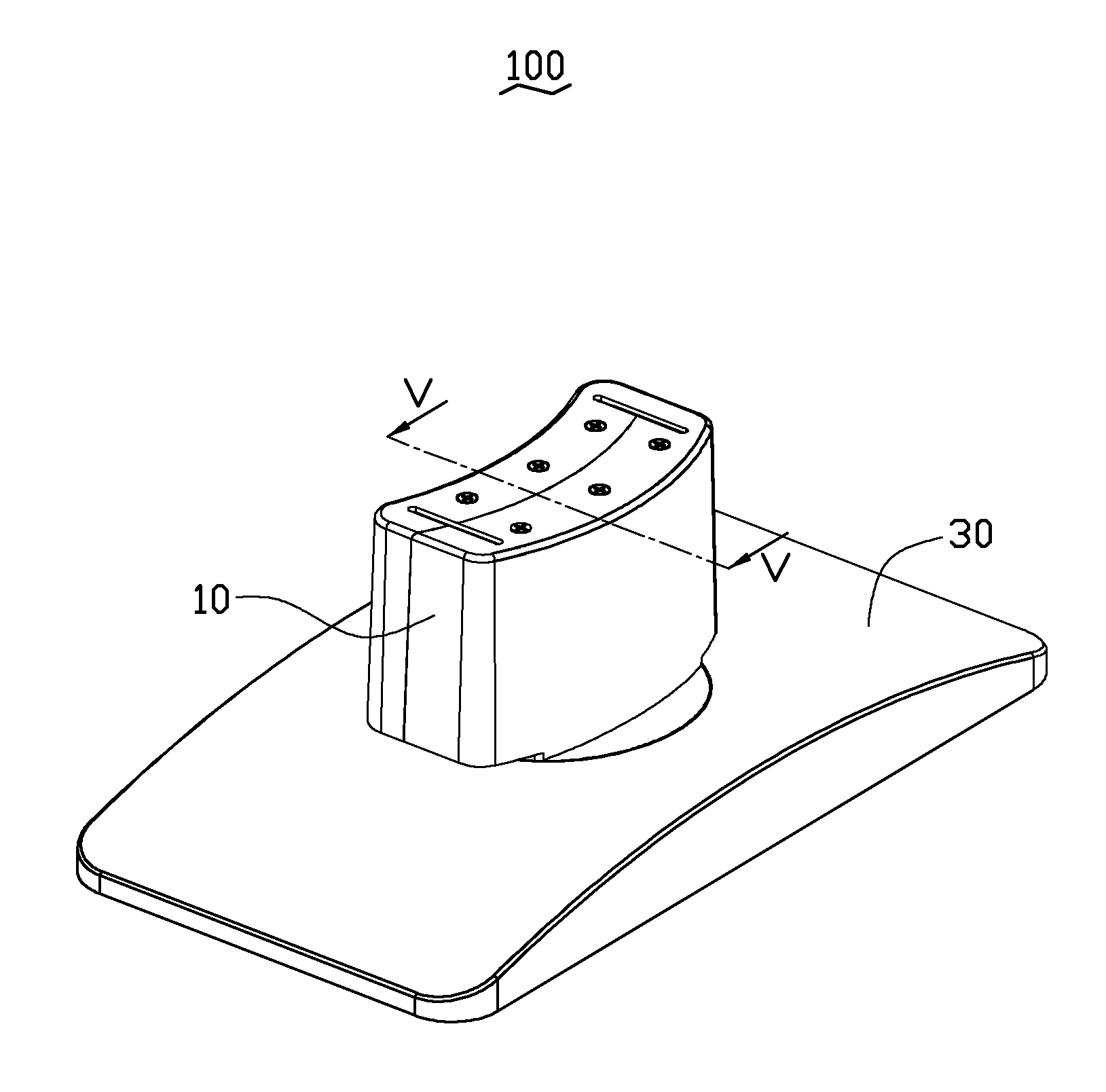
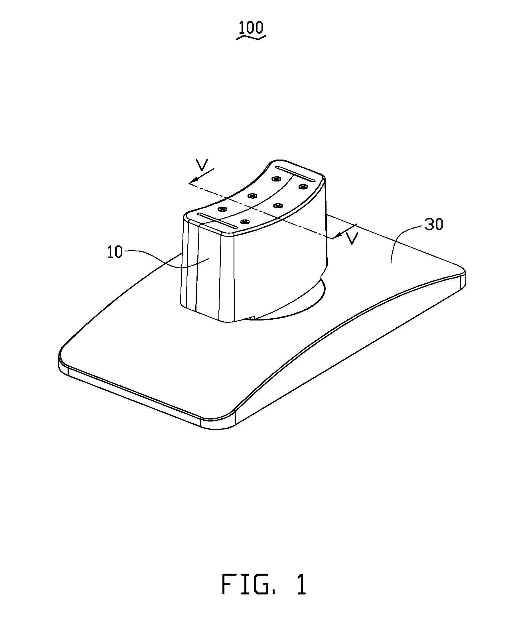
[0014]Referring to FIG. 1, an embodiment of a support stand 100 includes a bracket 10 and a base 30 connected to the bracket 10. The support stand 100 as disclosed may be used with a flat-panel display.

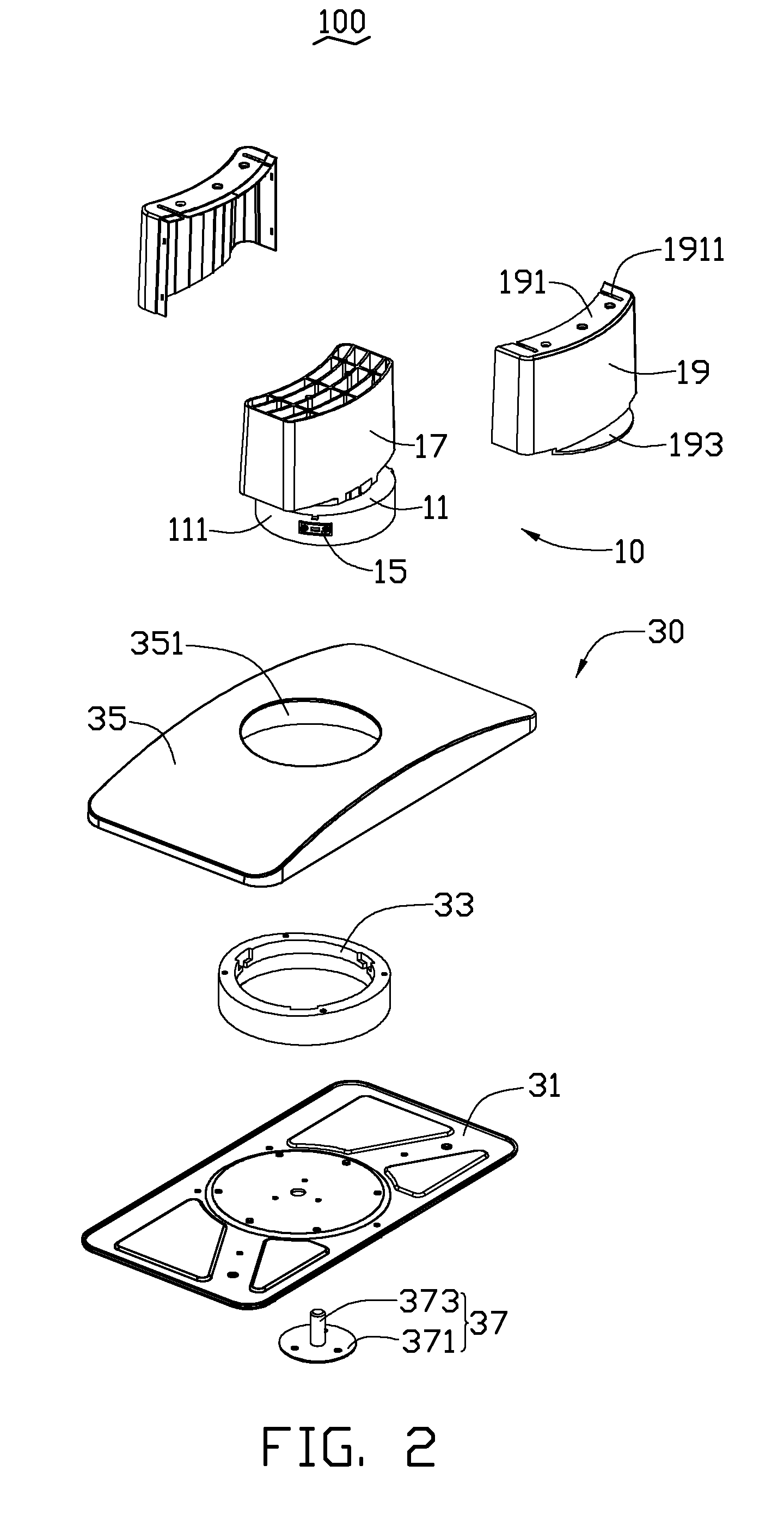
[0015]Referring to FIGS. 2 and 3, the bracket 10 includes a main body 11, two resilient members 13, a movable member 15, a support portion 17, and a shell 19 on the outside of the support portion 17.

[0016]The main body 11 has an outer surface 111, a receiving slot 113, two guide bars 115, and a restricting protrusion 117. The restricting protrusion 117 extends from the outer surface 111, and the receiving slot 113 is defined from the outer surface 111 into the interior of the main body 11. The guide bars 115 are substantially parallel and received in the receiving slot 113. The guide bar 115 includes an inner fastener hole 1151. The restricting protrusion 117 is opposite to the receiving slot 113. In the illustrated embodiment, there are three receiving slots 113, three restricting pr...


PUM


Abstract

A support stand includes a bracket and a base connected with the bracket. The bracket includes a main body, a movable member, and a resilient member. The main body defines a receiving slot therein, and the movable member is partially received in the receiving slot, with opposite ends of the resilient member resisting the main body and the movable member. The base includes a latching member sleeved on the main body of the bracket. The latching member includes a latching portion for impelling and guiding the movable member to be received in the receiving slot of the main body, and the movable member to contact the resilient member. After the movable member passes over the latching portion, an elastic force created by the resilient member extends the movable member from the receiving slot of the main body, and the movable member is latched in the base.

Description

BACKGROUND[0001]1. Technical Field[0002]The present disclosure generally relates to display devices and, particularly, to a support stand for a flat-panel display monitor.[0003]2. Description of Related Art[0004]A liquid crystal display monitor often includes a monitor and a support stand. A support stand often includes a bracket and a base for supporting the monitor and adjusting the angle or height of the monitor. The bracket and the base are often detachable to occupy minimal space and ease transport.[0005]A commonly used bracket often defines a slot, and the base includes a hook. The bracket and the base are assembled by the slot receiving the hook. However, since, during assembly, the hook is resiliently moved to be received in the slot of the bracket, whereby the hook must be sufficiently elastic to be able to resiliently move, and thereby may provide insufficient rigidity to ensure firm connection between the base and the bracket.[0006]Therefore, there is room for improvement...

Claims


Application Information

Patent Timeline
Patent Type & Authority Applications(United States)
IPC IPC(8): F16M11/04
CPCF16M11/00F16M2200/08F16M11/22F16M11/08
Inventor LIU, ZHI-BINCHEN, XUE-MINGDUAN, JUN-WU
Owner HONG FU JIN PRECISION IND (SHENZHEN) CO LTD
Why Eureka
Try Eureka