Tool Holder Having An Arrangement For Delivering Coolant And Transmitting Electric Power

a technology of electric power transmission and tool holder, which is applied in the field of tool holder, can solve the problems of long tool holder, reduce the path for transmitting electric power, and eliminate the undesired vibration of the tool holder by high frequency vibration,

Inactive Publication Date: 2020-09-03
XPOLE PRECISION TOOLS
View PDF0 Cites 0 Cited by
  • Summary
  • Abstract
  • Description
  • Claims
  • Application Information

AI Technical Summary

Benefits of technology

[0007]It is therefore one object of the invention to provide a tool holder having an arrangement for delivering coolant and transmitting electric power wherein the actuator is disposed in the tool mounting member so that the path for transmitting electric power can be greatly decreased. Further, undesired vibration to the tool holder by the high frequency vibration may be eliminated. Furthermore, the inadequate rigidity of the material of the conventional tool holder having a high L / D ratio is improved. In addition, smoothness and quality of the workpiece are improved. In addition, coolant delivery through the first channel and wire passing through the second channel for transmitting electric power are made independently. Additionally, the provision of the sleeves may lengthen the tool holder if such need arises.
[0008]It is another object of the invention to provide a tool holder having an arrangement for delivering coolant and transmitting electric power wherein the inadequate rigidity of the material of the conventional tool holder having a high L / D ratio is improved, and the high L / D ratio is significantly decreased. As shown in FIG. 1, the length to diameter ratio before the installation of the actuator labeled L1 / D is decreased to L / D after the installation of the actuator. Further, the provision of at least one sleeve can lengthen the tool holder while the L / D is fixed irrespective of the value of L1.

Problems solved by technology

Additionally, the provision of the sleeves may lengthen the tool holder if such need arises.

Method used


Image

  • Tool Holder Having An Arrangement For Delivering Coolant And Transmitting Electric Power
  • Tool Holder Having An Arrangement For Delivering Coolant And Transmitting Electric Power

Examples


Embodiment Construction

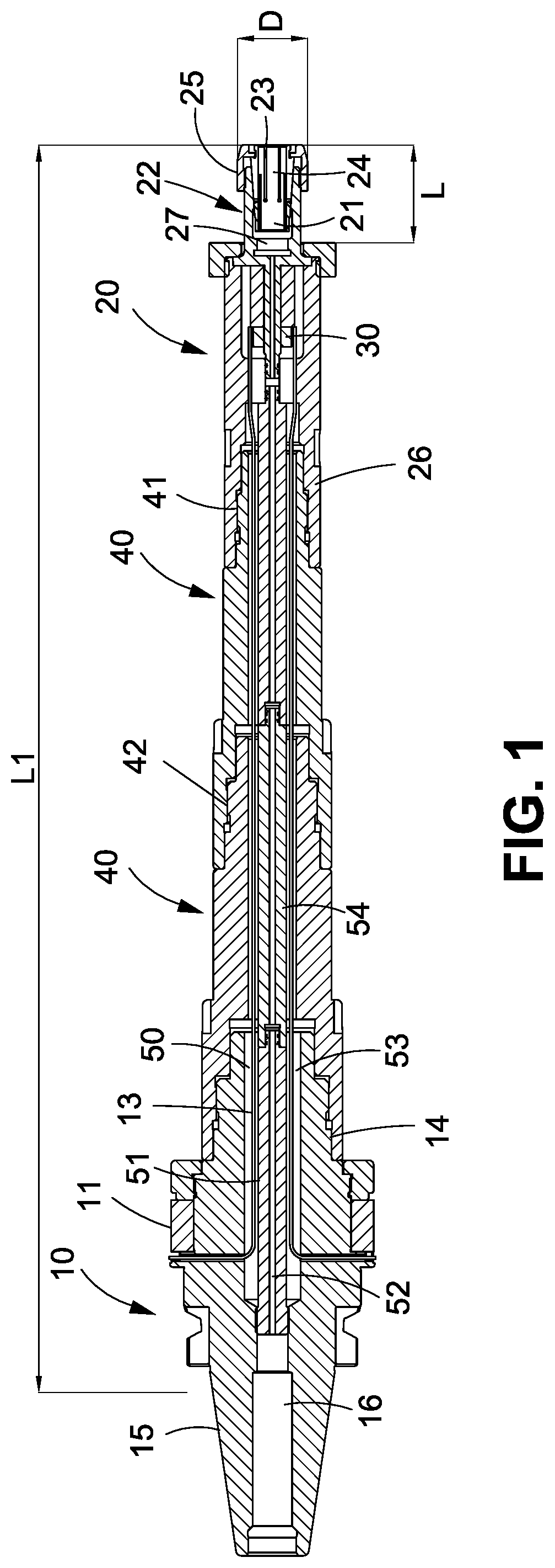
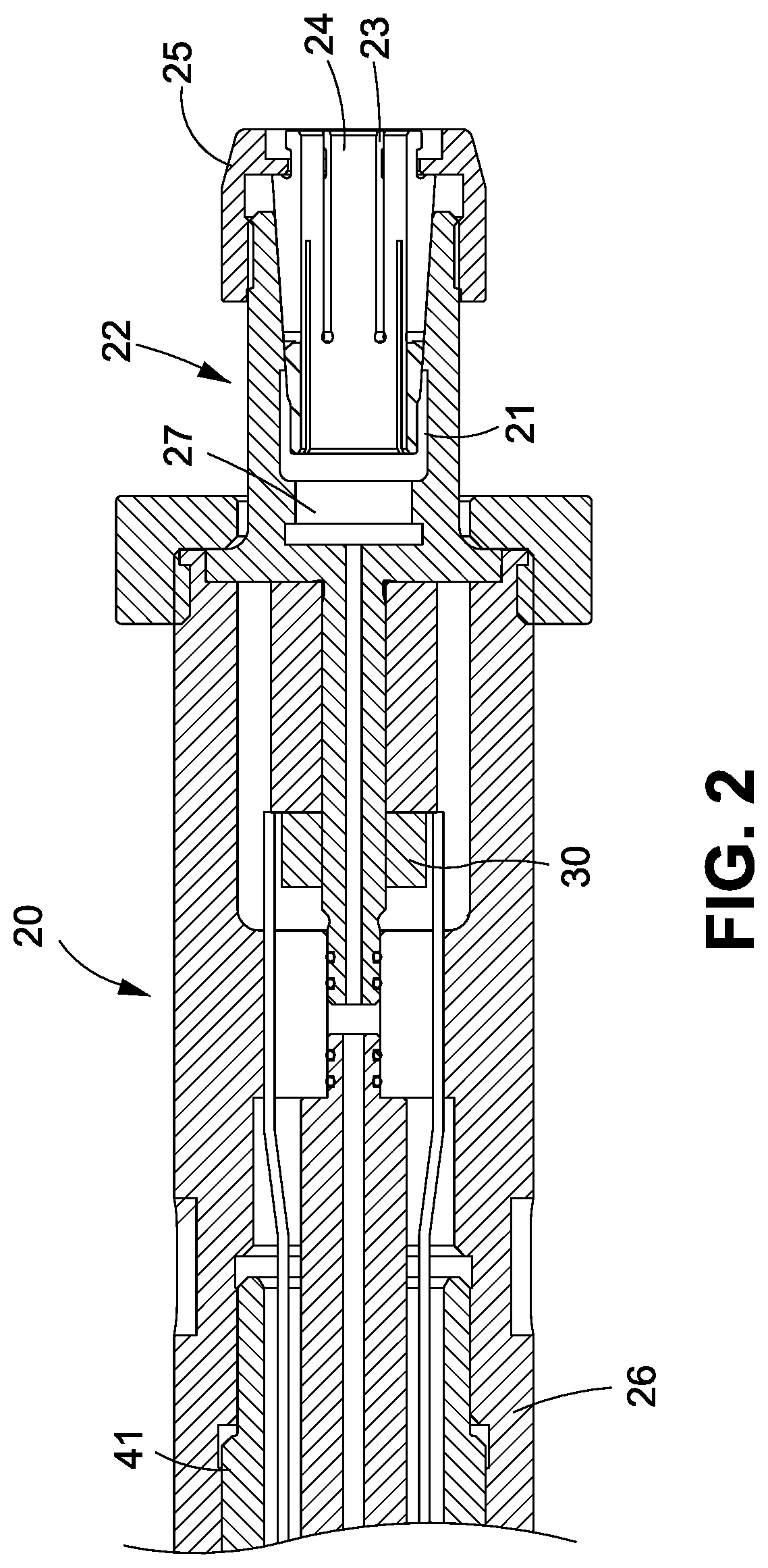
[0021]Referring to FIGS. 1 and 2, a tool holder having an arrangement for delivering coolant and transmitting electric power according to the invention is used in a machine which supplies power via a spindle (not shown). The tool holder comprises a connector 10 received in the spindle, a conductive ring 11 disposed on the connector 10 and electrically connected to the spindle so that power may be supplied to the tool holder; a substantially cylindrical tool mounting member 20 including an axial hole 21 for fastening a portion of a tool (e.g., tool handle but not shown); and an actuator 30 disposed in the tool mounting member 20 and electrically connected to the conductive ring 11 so that power may be supplied to the actuator 30. The produced vibration of high frequency is transmitted to the tool via the axial hole 21.

[0022]The tool holder further comprises an axial passageway 50 through both the connector 10 and the tool mounting member 20, and a waterproof dividing member 51 for di...


PUM

PropertyMeasurementUnit
poweraaaaaaaaaa
electric poweraaaaaaaaaa
forceaaaaaaaaaa

Abstract

A tool holder used in a machine which supplies power via a spindle and deliveries coolant is provided with a connector in the spindle; a conductive ring on the connector and electrically connected to the spindle so as that power is configured to supply to the tool holder; a tool mounting member including an axial hole for fastening a portion of a tool; an actuator in the tool mounting member and electrically connected to the conductive ring so that power is transmitted to the tool via the axial hole; an axial passageway through both the connector and the tool mounting member; and a waterproof dividing member for dividing the axial passageway into a first channel for delivering coolant and a second channel for passing a wire. The first channel is spaced from the second channel so that electric power transmission and coolant delivery are made independently.

Description

BACKGROUND OF THE INVENTION1. Field of the Invention[0001]The invention relates to relates to tool holders and more particularly to a tool holder having an arrangement for delivering coolant and transmitting electric power.2. Description of Related Art[0002]Conventional high precision machining including drilling, milling, boring, cutting and polishing often uses computer numerical control (CNC) machine as an auxiliary device in cooperation with tools such as drills, cutters, or the like. The tools are shaped as an elongated handle. A tool holder may secure the tool to the spindle of the CNC machine. The spindle rotates in high speed to rotate the tool fastened by the tool holder for machining a workpiece.[0003]Typically, coolant is used to cool and lubricate a workpiece being machined so as to obtain the following benefits; keeping the workpiece at a stable temperature. Very warm is acceptable, but extremely hot or alternating hot-and-cold are avoided. maximizing the life of the cu...

Claims


Application Information

Patent Timeline
Patent Type & Authority Applications(United States)
IPC IPC(8): B23Q11/10B23Q11/00
CPCB23Q2220/006B23Q11/1023B23Q11/0032B23Q1/0036B23B31/02B23B2250/12B23B2270/10B23B31/2072
Inventor CHEN, PETER
Owner XPOLE PRECISION TOOLS
Why Eureka
Try Eureka