Electrical generator

Inactive Publication Date: 2011-05-19
BLEVINS JERRY
View PDF14 Cites 12 Cited by
  • Summary
  • Abstract
  • Description
  • Claims
  • Application Information

AI Technical Summary

Problems solved by technology

These concerns include the noise and pollution associated with the genera

Method used


Image

  • Electrical generator
  • Electrical generator
  • Electrical generator

Examples


Embodiment Construction

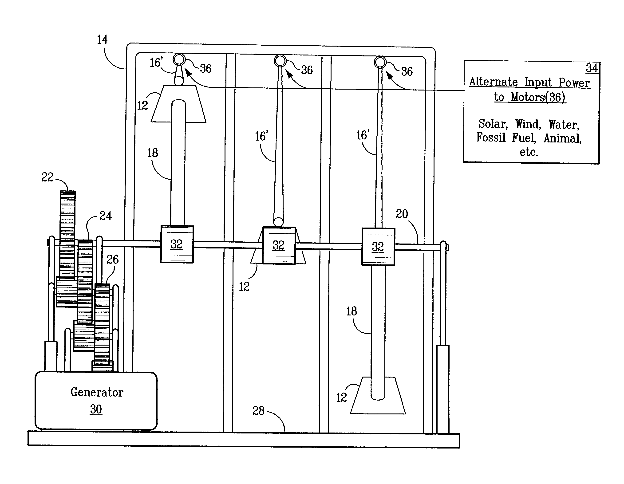
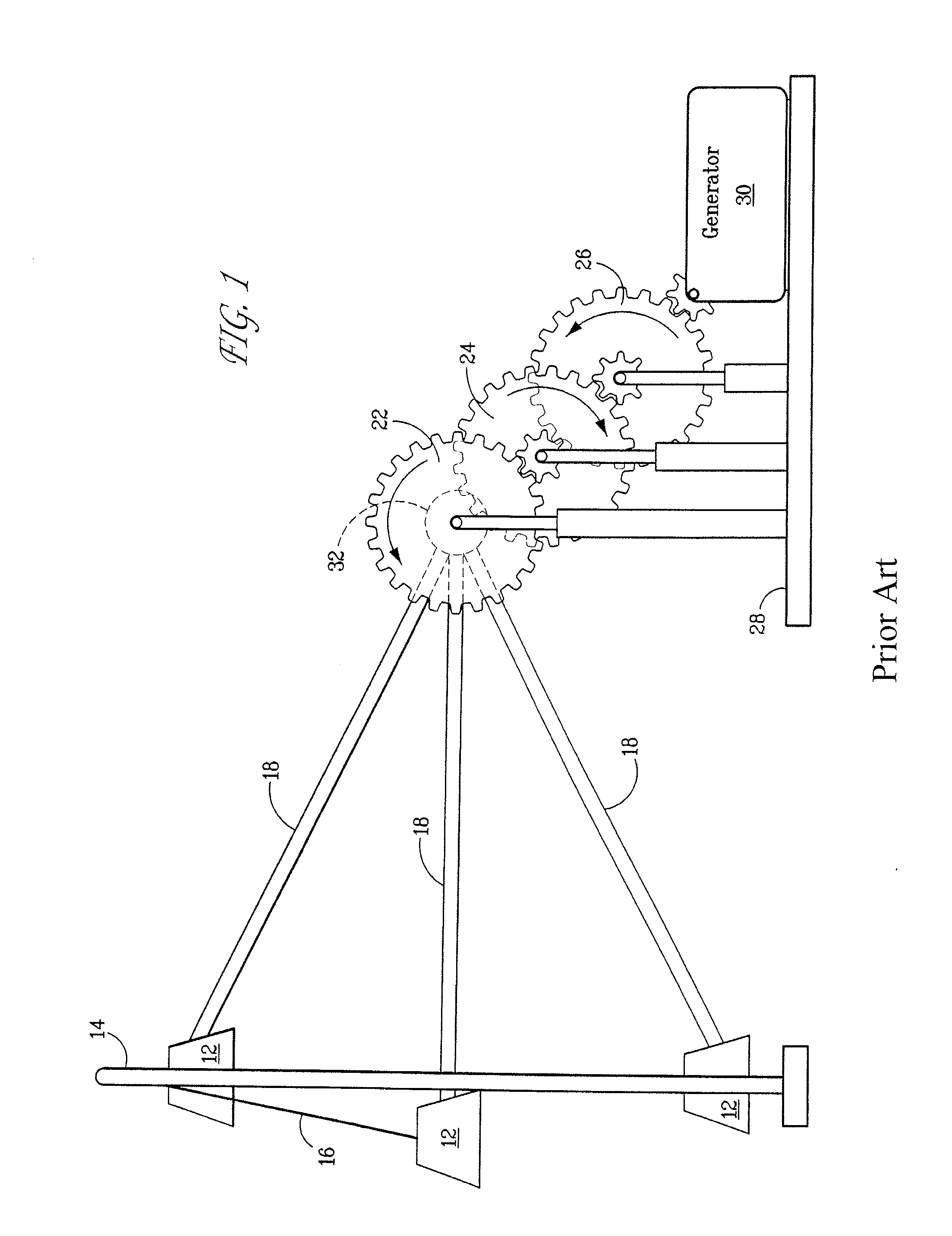
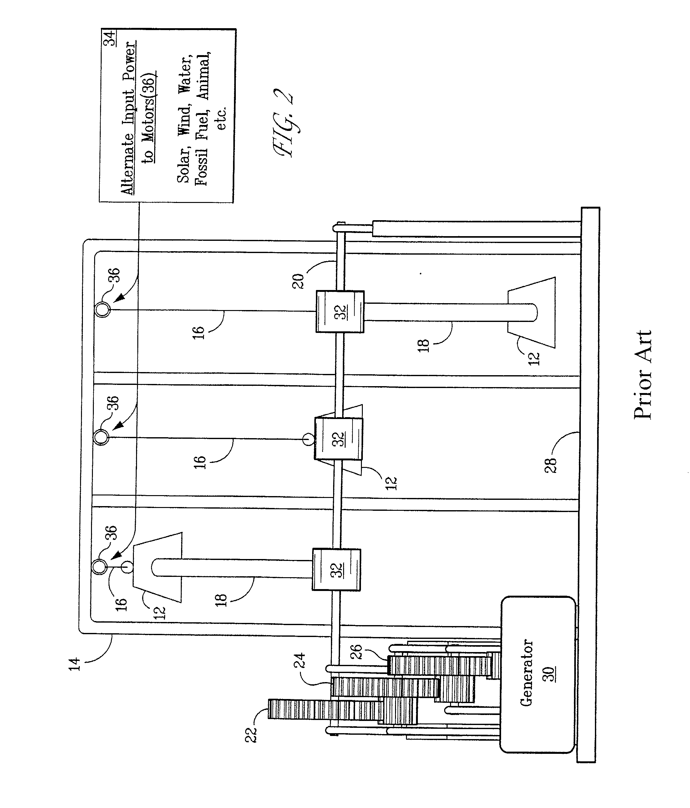
[0023]As described in U.S. Pat. No. 7,709,970 and incorporated herein by reference, a series of weights 12 are connected to a rack 14. While three weights are shown, any number of weights may be utilized. An arm 18 is provided between each weight 12 and a longitudinal shaft 20. The end of the arm 18 moves in an arc while the weight 12 moves in a line. To account for this difference, the arm 18 attaches to the weight in any suitable manner. The end of the arm 18 may attach to the weight by a cable or a rod pivotally connected to the weight, the arm, or both. Also, the arm may be made of telescoping sections, allowing the length of the arm to vary.

[0024]The shaft 20 is connected to a first gear 22. The first large gear 22 intermeshes with a second large gear 24, through the use of a compound gear, a small gear turning with the larger gears 22, 24. As the first gear 22 meshes with the smaller gear, an increase in rotational speed is gained. The larger gear 24 connects with a third larg...


PUM


Abstract

An electrical generator powered by the rotation of a central shaft. A gear train rotates with respect to the central shaft and is in operable connection to a generator for producing electrical energy. The shaft can be rotated by falling weights connected to longitudinal arms. Alternatively, a motor can be used to rotate a relatively large wheel in operable connection with the series of gears or gear train. Additionally, the shaft can be rotated by a renewable energy source, such as wind or water.

Description

CROSS-REFERENCE TO RELATED APPLICATION[0001]This application claims the benefit of U.S. provisional patent application Ser. No. 61 / 272,918, filed Nov. 19, 2009.FIELD OF THE INVENTION[0002]The present invention is directed to an electrical generator.BACKGROUND OF THE INVENTION[0003]The generation and transmission of electrical power is a constant concern. Providing electrical power for the numerous needs of residential, commercial and industrial applications is a constant concern. These concerns include the noise and pollution associated with the generation of electricity and the problems in transmission over long distances.SUMMARY OF THE INVENTION[0004]In a first embodiment, an electrical generator utilizes power produced by falling weights. Falling weights are connected to long arms which turn a shaft. The shaft, through a series of gears, thereby rotates the poles / coils of the generator to produce electrical energy.[0005]A second embodiment of the present invention utilizes a moto...

Claims


Application Information

Patent Timeline
IPC IPC(8): H02K7/116
CPCH02K7/116H02K7/1861H02K7/1853H02K7/1807
Inventor BLEVINS, JERRY
Owner BLEVINS JERRY
Why Eureka
Try Eureka