Hydro-wind power generating turbine system and retrofitting method

a technology of hydro-wind power generation and turbines, which is applied in the direction of electric generator control, greenhouse gas reduction, fluid couplings, etc., can solve the problems of the torque required of the motor to rotate the generator, and achieve the effects of reducing wind speed, reducing wind speed, and producing more kilowatt hours

Inactive Publication Date: 2010-02-02
PERRY ROBERT NELSON
View PDF8 Cites 92 Cited by
  • Summary
  • Abstract
  • Description
  • Claims
  • Application Information

AI Technical Summary

Benefits of technology

[0008]Using hydraulics as an intermediary between the wind turbine shaft and the generator has several advantages. An unloading valve can be placed between the pressure and return hydraulic lines at ground level, to allow the turbine blades to start rotating at a lower wind speed. As the inertia of the blades is overcome by the wind, the unloading valve can be closed, causing the hydraulic oil to flow through the pump and rotate the generator. This can provide start-up of the generator at lower wind speeds, producing more kilowatt-hours.
[0009]The wind turbine blade speed of rotation can be controlled with a variable control valve partially blocking the high-pressure line from the hydraulic pump, or, it can act as a brake for the blades by completely closing the high-pressure line. To prevent impacting the generator at start-up when the blades are already turning, a small accumulator can be inserted in the high-pressure line. The accumulator can also be used to provide power to overcome the generator inertia at start-up by allowing the accumulated high-pressure oil stored in the accumulator to actuate the hydraulic motor for a short period of time. This helps in overcoming the initial start-up rotation of the generator.
[0012]Without the upper portion of the wind turbine in electrical contact with the ground, it is less likely the blades will be struck by lightning, reducing maintenance and structural damage. The cost of the blades will also be reduced, as there will be no need for internal metal conductors to prevent lightning from burning holes in the blades.

Problems solved by technology

The limitation is the torque required of the motor to rotate the generator.

Method used


Image

  • Hydro-wind power generating turbine system and retrofitting method
  • Hydro-wind power generating turbine system and retrofitting method
  • Hydro-wind power generating turbine system and retrofitting method

Examples


Embodiment Construction

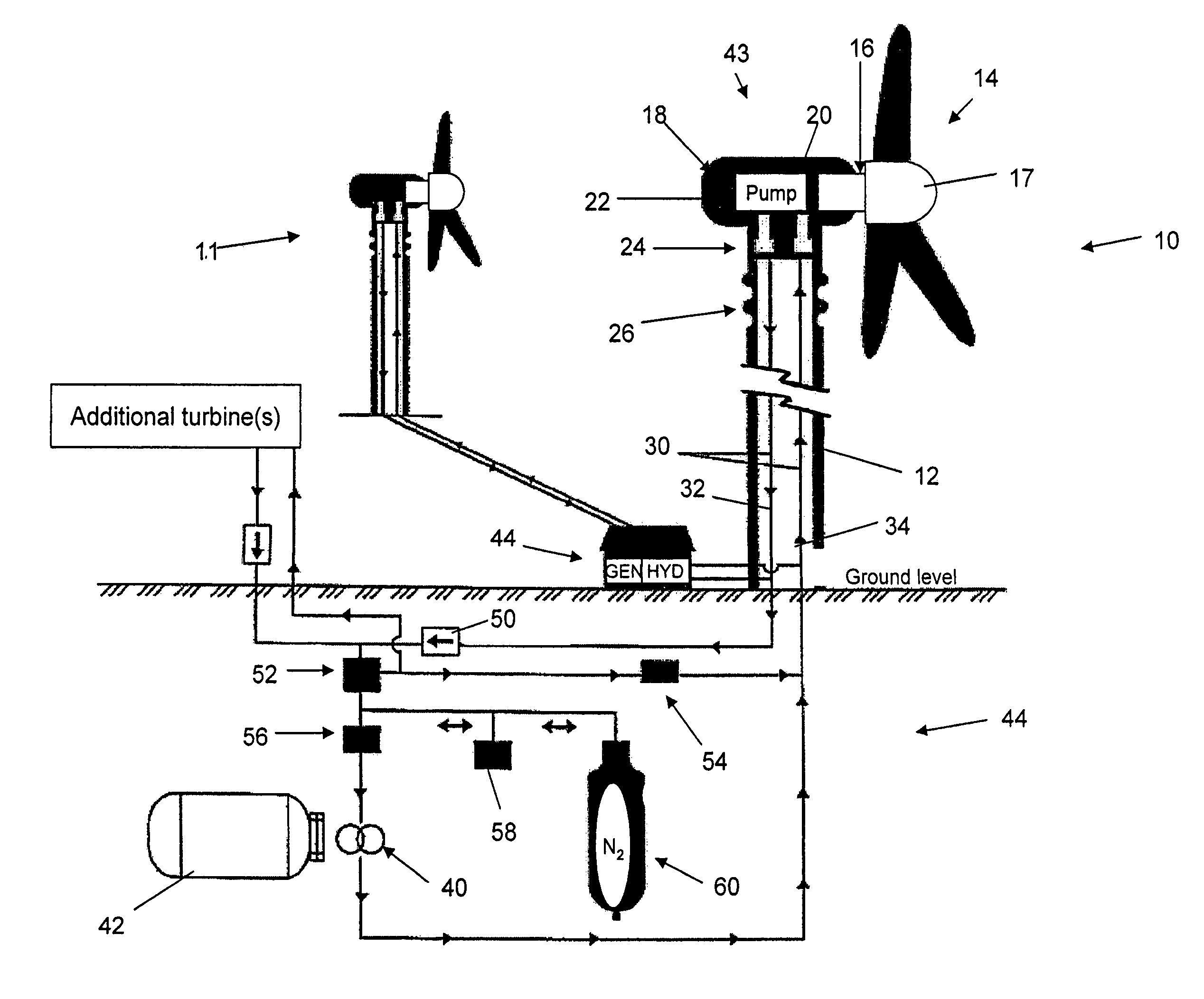
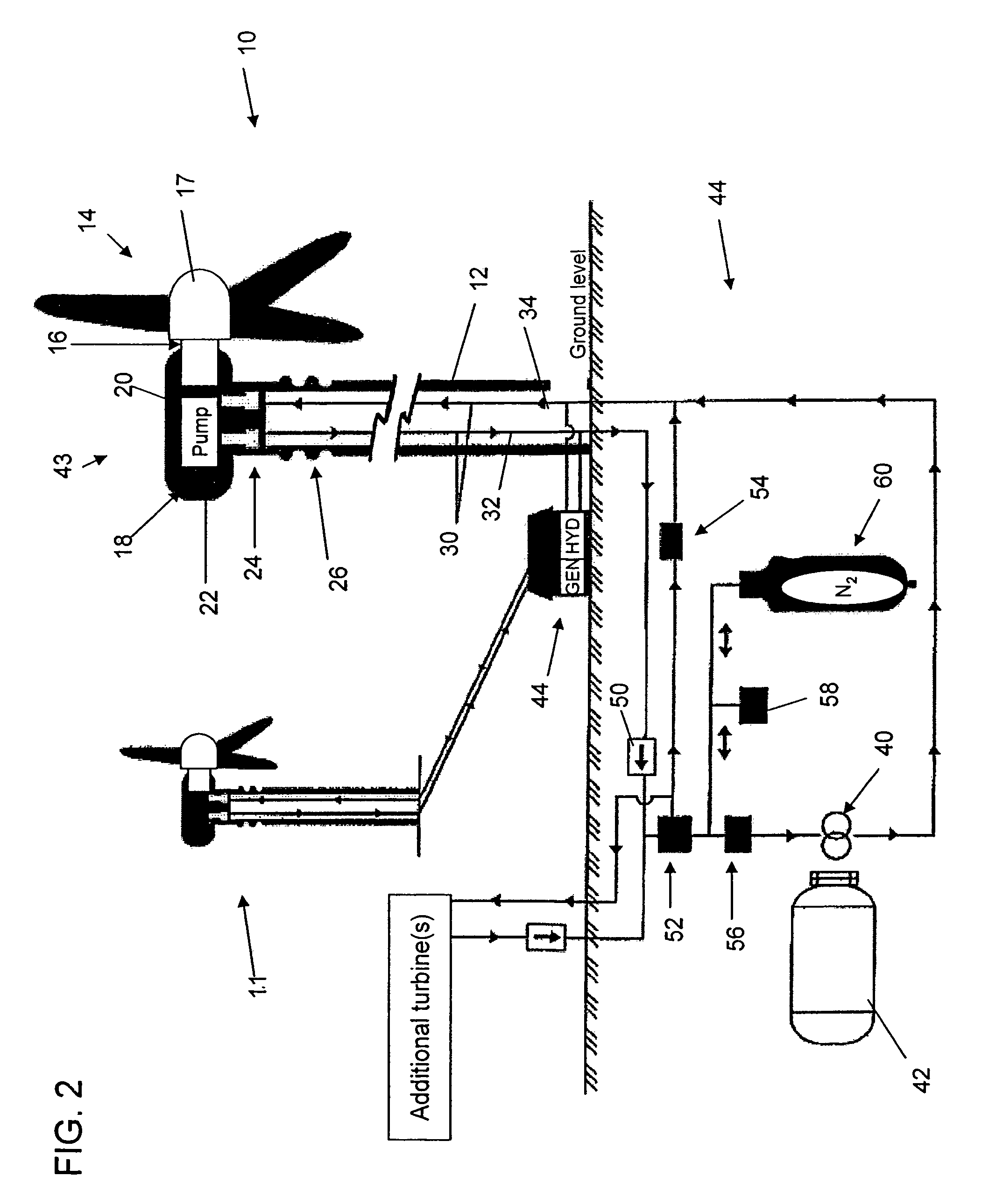
[0017]As shown in FIG. 2, there is provided a wind turbine system 10 in accordance with one embodiment of the present invention. The system includes a tower 12 having a blade and / or propeller arrangement 14 including at least two and typically three blades mounted on a blade shaft 16 with a hub member 17, wherein the blade shaft is mechanically coupled to a hydraulic pump 20 maintained within nacelle 18. Hydraulic pump forms part of the hydraulic transmission system of the present invention. Hydraulic transmission system includes an above-ground transmission component 43 and a ground level transmission component 44, with above-ground transmission component including the pump 20 and reservoir 22 with an appropriate suction line between the two as is known in the art.

[0018]The pump 20 is a variable displacement pump, such as a radial piston pump, wobble plate pump, swash plate pump or a bent axis pump, for example, and the pump works in a rotary fashion, whereby it develops a partial ...


PUM


Abstract

An electrical power producing wind turbine eliminates the possibility of being struck by lightning, reduces the complexity of gear trains and simplifies maintenance at heights. The wind turbine is electrically isolated from ground to reduce the possibility of being struck by lightning and the generator is located at ground level to simplify maintenance. The turbine blade shaft is directly attached to a hydraulic pump. The hydraulic fluid is transmitted to ground level through dielectric tubing and acts both as an electrical isolating medium and a transmitter of mechanical energy to the generator located at ground level. The wind turbine blade, shaft and hydraulic pump are electrically isolated from the support structure at the upper end.

Description

FIELD OF THE INVENTION[0001]The present invention relates to wind turbines, and more particularly to a wind turbine having a hydraulic transmission and an associated method for retrofitting standard wind turbine systems.BACKGROUND OF THE INVENTION[0002]Electrical power producing wind turbines are a supplement to power generating stations using fossil fuels or nuclear fuel to produce electricity. The primary components of current wind turbines are blades, blade shafts, a gear train and a generator. The gear train increases the speed of rotation of the shaft to run the generator at higher speeds of rotation than the turbine blades are rotating. The gear train and the generator combine to weigh more than twenty tons in many modern wind turbine implementations. A sample gear train is shown at 60 in FIG. 1, with the blade shaft 61 being coupled with a larger gear 62, which can then interact with appropriately sized intermediate gears 63 and a generator shaft gear 64 to drive the generato...

Claims


Application Information

Patent Timeline
Patent Type & Authority Patents(United States)
IPC IPC(8): F03B9/00H02P9/04
CPCF03D11/02F05B2260/406Y02E10/722F03D15/00F03D15/20F03D9/28F03D9/25F03D9/17F03D13/20Y02E10/72Y02E60/16Y02P80/10Y02E70/30
Inventor TORRES, ROSALIAPERRY, E. ROBERT
Owner PERRY ROBERT NELSON
Why Eureka
Try Eureka