
Geared wheel motor design

a geared wheel and motor technology, applied in the direction of gearing, mechanical equipment, transportation and packaging, etc., can solve the problems of poor machine efficiency, and achieve the effect of reducing the stress on the undercarriage and other aircraft components, and reducing tire wear

Inactive Publication Date: 2008-12-30
BOREALIS TECH LTD
View PDF38 Cites 95 Cited by
  • Summary
  • Abstract
  • Description
  • Claims
  • Application Information

AI Technical Summary

Benefits of technology

The present invention is a small compact gearing system that can be located in or near a drive wheel, and provide the necessary torque with reasonable system mass. Additionally, a mechanism that allows the high gear ratio to automatically de-couple the motor from the load is required. The invention uses a compound planetary gear system with two available gear ratios, and a ratchet mechanism for automatic gear reduction in the event of an overhauling load. The invention also includes a locking mechanism for the high gear ratio, and the use of gear rings instead of sun gears. The invention harnesses the enhanced capabilities of a mesh-connected polyphase motor system to provide high levels of torque for moving from stationary or low speed, and low levels of torque at higher speeds. This eliminates the need for separate tractor units and can be used to pre-rotate the wheels prior to landing to reduce tire wear and impact stress to undercarriage and other aircraft components.

Problems solved by technology

The use of small compact electric motors inside, or in close proximity to, a wheel for direct drive has a number of problems.
The active materials of the machine will be underutilized, the machine will be far heavier than necessary, and the machine efficiency will be poor.
This presents a significant problem, because, in these cases, the load may be rotating faster than the motor and may accelerate the motor via the gearing system.

Method used


Image

  • Geared wheel motor design
  • Geared wheel motor design
  • Geared wheel motor design

Examples


Embodiment Construction

[0025]Embodiments of the present invention and their technical advantages may be better understood by referring to FIGS. 1-7.

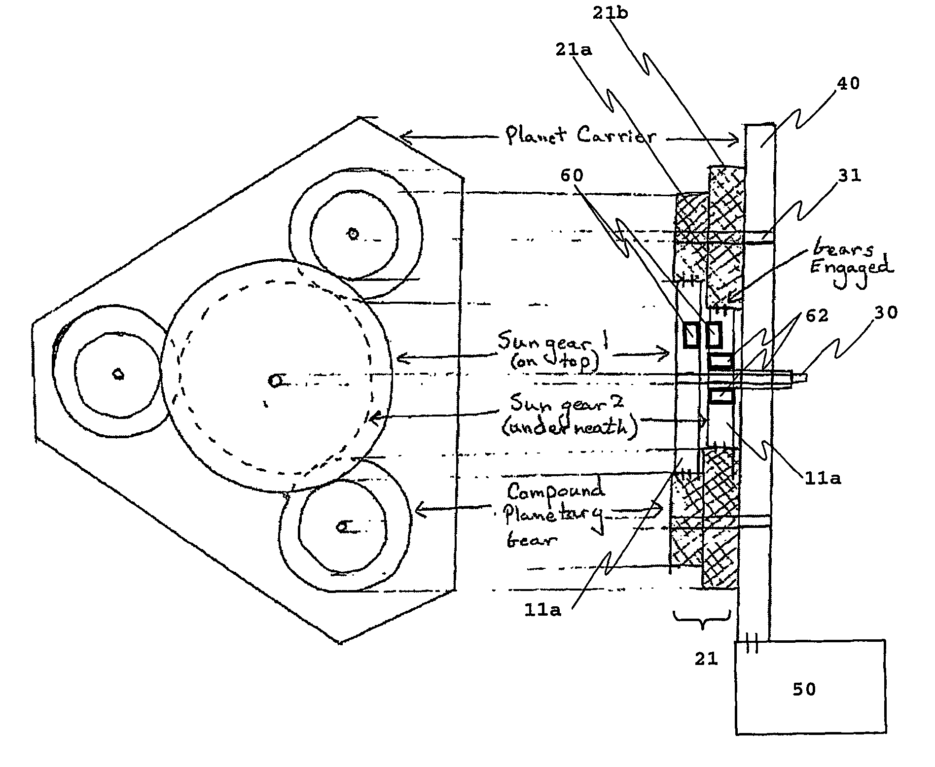
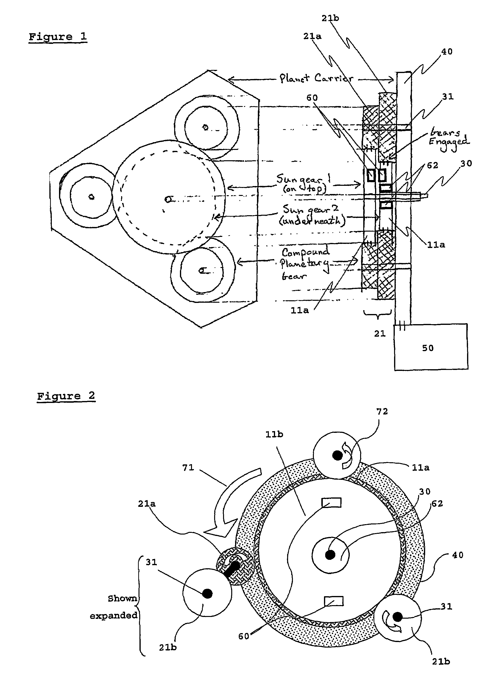
[0026]Referring now to FIGS. 1 and 2, which show diagrammatic representations of a gear system of the present invention useable in a variety of settings, three compound planetary gears 21 all share identical features, and are disposed evenly around a sun gear axis 30. The planetary gears 21 are compound, and consist of two coaxial circular spur gears 21a, and 21b, of different pitch diameter (shown in expanded view in FIG. 2). The coaxial circular spur gears 21a, and 21b are fixedly connected together, or formed initially as a single unit, so that they are only able to rotate as a single unit. The number of compound planetary gears (3 shown here) will be application dependent, with respect to size and torque considerations. For the sake of clarity the gear teeth are not shown. The teeth may be any type of gear teeth known in the art, for example, spur or helic...


PUM


Abstract

The present invention is a compound planetary gear system which has a moveable sun gear and a lockable sun gear to change the gear ratio between a high gear ratio and a pseudo 1:1 slipping ratio. The system makes use of a ratchet and pawl mechanism to provide a safety backup for when the lockable sun gear is locked. The invention may be used to move the aircraft from a stationary position, for taxiing, and for pre-rotating the wheels prior to landing.

Description

CROSS-RERERNCE TO RELATED APPLICATIONS[0001]This application is the U.S. national stage application of International Application PCT / US04 / 033217, filed Oct. 6, 2004, which international application was published on Apr. 21, 2005, as International Publication WO2005 / 035358 in the English language. The International Application claims the benefit of application Ser. No. 60 / 510,423, filed Oct. 9, 2003.TECHNICAL FIELD[0002]The present invention relates generally to gearing systems for motors, particularly to planetary gearing systems for electric motors. The present invention relates to aircraft landing gears, and more specifically to self-powered ground wheels of aircraft. The present invention also relates to systems for pre-rotating the landing gear wheel prior to landing.BACKGROUND ART[0003]U.S. Pat. No. 3,711,043 to Cameron-Johnson discloses an aircraft drive wheel having a fluid-pressure-operated motor housed within the wheel and two planetary gear stages housed in a gear box outb...

Claims


Application Information

Patent Timeline
Patent Type & Authority Patents(United States)
IPC IPC(8): B64C25/40F16H48/06
CPCF16H3/56B64C25/405Y02T50/823Y02T50/80
Inventor EDELSON, JONATHAN SIDNEY
Owner BOREALIS TECH LTD
Learn More